 Skip to main content Skip to footer
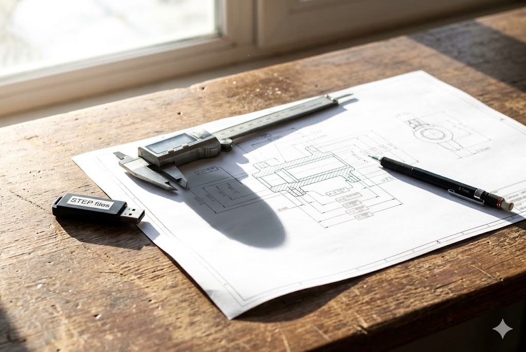
Every week, our team reviews RFQs from buyers who send only a STEP file — no drawing, no tolerance callouts, no surface finish requirements. We quote what we see. Then the first article arrives, and the disputes begin.
You should always provide both a 3D STEP file and a 2D PDF drawing when requesting CNC quotes from China. The 3D model defines geometry for CAM programming, while the 2D drawing communicates tolerances, GD&T, surface finish, and material specifications that no 3D file can convey on its own. Together, they eliminate guesswork and protect you legally.
Most sourcing problems do not start on the shop floor. They start at the RFQ stage. Send the right files and you prevent 80% of them before production begins.
Which Format Do Suppliers Rely on More for Machining?
When we receive a new inquiry, the first thing our engineers do is open the 2D drawing — not the 3D model. The drawing tells us what matters: tolerances, datums, surface finish, and material grade.
Suppliers rely on the 2D drawing more than the 3D model during machining. The 3D file drives the CAM software and toolpath generation, but the 2D drawing is the reference document for estimators during quoting, for machinists during production, and for quality inspectors during final inspection. It is the authoritative source for manufacturing intent.
Who Uses What, and When
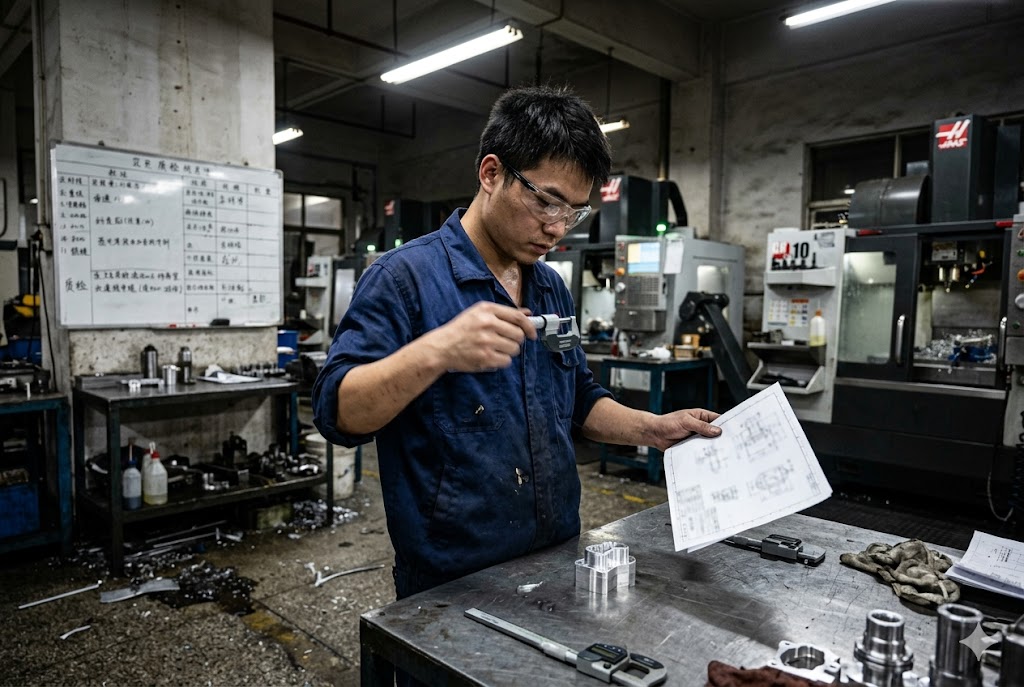
Think of your files as serving two separate audiences. The machine reads the 3D model. The people read the 2D drawing.
Here is how each document is used across the production workflow:
| Stage | Person Responsible | Primary Document Used |
|---|---|---|
| Quoting | Estimator / Sales Engineer | 2D Drawing |
| CAM Programming | CNC Programmer | 3D Model (STEP) |
| Machining | Operator | 2D Drawing (key dimensions) |
| In-Process Inspection | QC Technician | 2D Drawing |
| First Article Inspection | QA Engineer | 2D Drawing |
| Non-Conformance Review | Engineering / Management | 2D Drawing |
This table shows a clear pattern. The 3D model is used once — during CAM programming 1. The 2D drawing is referenced at every other stage. If your drawing is missing or incomplete, every one of those people is forced to guess.
Why the 2D Drawing Functions as a Legal Document
Our supply chain team has handled non-conformance disputes between clients and factories. In every case, the 2D drawing — not the 3D model — is the document used to judge conformance. If your drawing does not specify a tolerance, the factory defaults to its own general tolerance standard, typically ISO 2768-m 2 or equivalent. If the dimension is out of your expected range but within their default standard, they are not wrong. You have no legal ground.
This is why we tell every client: the 2D drawing is the contract. It is more important than the 3D model for production orders.
What Happens When Only the 3D Model Is Sent
When a buyer sends only a STEP file, the factory must make a series of assumptions:
- What tolerances apply to critical features?
- What surface finish is required?
- What material grade is needed?
- Which face is the datum for inspection?
- Which features are critical-to-quality?
None of these questions can be answered by measuring a 3D model. A supplier will either guess, apply their default standards, or ask — and if they ask, your response time becomes part of the lead time. Incomplete files slow everything down.
Can 3D Files Replace Detailed Drawings?
In short — no. But the longer answer depends on part complexity. We have machined simple prismatic brackets from a 2D drawing alone. We have never successfully machined a complex part from a 3D model alone without errors in the first run.
A 3D file cannot replace a detailed 2D drawing for CNC machining purposes. While a STEP file is essential for CAM programming, it cannot communicate critical manufacturing data such as tolerances, GD&T symbols, surface finish callouts, thread specifications, and material grades. These must always be specified in a 2D drawing.
What a 3D Model Cannot Communicate
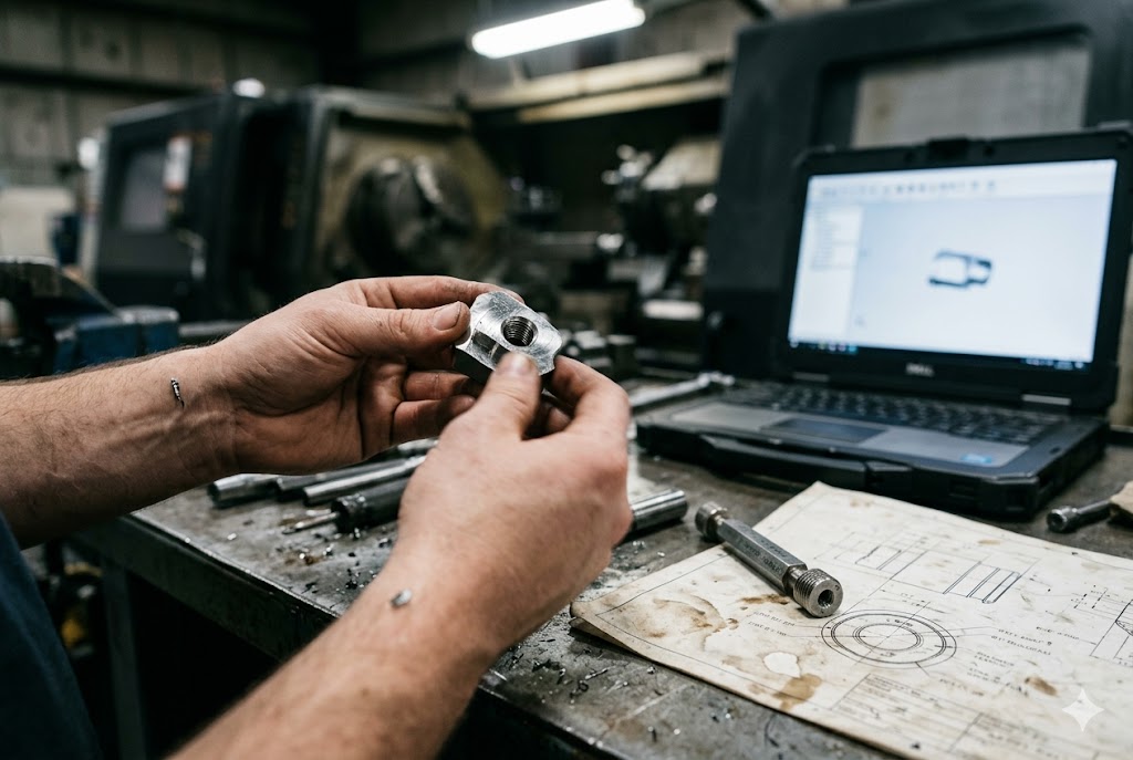
Let us be specific. Here is a breakdown of manufacturing information that a 3D model simply does not contain:
| Information Type | Visible in 3D Model? | Must Be in 2D Drawing? |
|---|---|---|
| Dimensional tolerances (e.g., ±0.01mm) | No | Yes |
| GD&T callouts (flatness, perpendicularity, etc.) | No | Yes |
| Surface finish (Ra value, machining marks) | No | Yes |
| Thread type and class (e.g., M8×1.25, 6H) | Geometry only | Yes |
| Material specification (e.g., 6061-T6 vs 6063) | No | Yes |
| Heat treatment or coating requirements | No | Yes |
| Critical-to-Quality (CTQ) feature callouts | No | Yes |
| Inspection datums | No | Yes |
Every row in this table is a potential defect if left unspecified. These are not minor details. Specifying the wrong material grade or omitting a surface finish callout 3 can cause part rejection, assembly failure, or warranty claims.
The Thread Problem
Threads are the clearest example of why 3D models fall short. A STEP file can model the geometry of a threaded hole. But it cannot specify thread class, fit, or manufacturing method. Is it cut thread or rolled thread? Is it 6H or 4H? Is the callout M6×1.0 or #10-32?
Our machinists cannot answer these questions from the 3D file. If they guess and get it wrong, the part fits nothing. If they ask, the timeline slips. If you assume they will figure it out, you will receive non-conforming parts.
When a 2D Drawing Alone Is Acceptable
There is one exception worth noting. For simple prismatic parts — flat plates, simple brackets, basic blocks — a well-dimensioned 2D drawing with no curved surfaces can be sufficient without a 3D file. The condition is that the drawing must include:
- All dimensions with tolerances
- Material specification
- Surface finish callouts
- Any hole, thread, or slot details
Even then, providing the 3D model alongside speeds up quoting for complex shops. Simple parts are faster to quote with a complete 2D drawing only.
Should I Always Provide Both for Clarity?
Yes — always. This is the single most consistent advice we give to every new client. Providing both documents eliminates the most common source of first-article failures.
You should always provide both a 3D STEP file and a 2D PDF drawing together for any CNC machining order from China. This combination gives the CAM programmer the geometry they need and gives every other team member — estimators, machinists, and inspectors — the manufacturing intent they need. No other combination delivers both.

The Instant Quote Platform Trap
Many buyers now use online instant quoting platforms to get fast prices from Chinese suppliers. These platforms price from the 3D geometry only. They calculate volume, identify features like holes and pockets, and return a price automatically.
The problem: that price reflects geometry cost, not manufacturing intent.
When a detailed 2D drawing with tight tolerances and finish requirements is added after an instant quote, the price almost always increases. Sometimes significantly. The 3D-only price is a best-case estimate. The 2D-informed price is the real production cost.
We have seen cases where a tight tolerance callout on a single critical bore — something like H7 fit tolerance 4 — added 20–35% to the part cost, because the feature required a finish boring operation and dedicated gauge inspection that the automated system did not account for.
How to Mark CTQ Features Effectively
Not every dimension on your drawing needs a tight tolerance. Applying tight tolerances uniformly across all features is a common mistake. It tells the machinist that everything is equally important — which means nothing gets prioritized.
Our recommendation: identify three to five Critical-to-Quality (CTQ) features on the drawing. Annotate them with a functional note explaining why they matter. This has two benefits:
- Machinists know where to focus attention and setup precision.
- Inspectors know which features require detailed measurement versus visual check.
Studies in precision machining environments have shown that blanket tight-tolerance callouts can inflate machining time and inspection cost by 40–80% compared to targeted tolerance allocation. Selective callouts reduce cost without reducing part performance.
File Format Summary
| File Type | Format to Send | Why |
|---|---|---|
| 3D Model | STEP (.stp or .step) 5 | Universal CAM compatibility |
| 2D Drawing | PDF (dimensioned, toleranced) | Human-readable, print-stable |
| 2D Drawing (editable) | DXF (optional) | For laser/waterjet flat parts |
| Native CAD | Avoid sending | Version and software incompatibility |
What Risks Come from Incomplete Drawings?
Incomplete drawings are the root cause of most first-article failures we handle. The risk is not theoretical. It costs real money, real time, and real relationships.
Incomplete or missing 2D drawings force Chinese suppliers to reverse-engineer your design intent, including workholding strategy, inspection datums, and surface finish priority. This guesswork is invisible during quoting but surfaces as defects at first article, causing rework costs, production delays, and non-conformance disputes that are difficult to resolve without a formal drawing as reference.

The Guesswork Chain
When a drawing is incomplete, a chain of guesswork begins. Each person in the production process fills in the gaps with their own assumptions:
- The estimator quotes based on general tolerances.
- The CAM programmer chooses workholding based on the 3D geometry alone.
- The machinist applies the shop's default surface finish.
- The inspector measures the features they think are important.
At no stage does anyone stop to confirm with the buyer. Lead times are tight. Questions slow things down. Most shops move forward with what they have.
The result: a part that looks correct in the 3D preview but fails your incoming inspection.
Prototype Stage: A Special Case
At prototype stage, it is common for the 2D drawing to be unfinished. Design intent is still evolving. In this situation, we advise clients to submit the STEP file with a clear label: "Prototype stage — DFM feedback requested."
This label does two things. It tells the supplier that design flexibility exists. And it signals that the supplier is invited to suggest cost-saving changes before the drawing is locked. In our experience, this approach consistently uncovers one or two design features that are expensive to machine but easy to modify — thin walls, unnecessary undercuts, or overly tight fits on non-functional surfaces.
DFM (Design for Manufacturability) 6 feedback at prototype stage is free. Changes after the drawing is locked cost time and money.
Common Incomplete Drawing Errors
| Missing Information | Consequence |
|---|---|
| No tolerance callouts | Factory applies ISO 2768-m default; critical fits may fail |
| No surface finish (Ra) specified | Machinist selects standard finish; may be too rough or too smooth |
| No material grade (e.g., 6061 vs 7075) 7 | Factory substitutes available stock; wrong mechanical properties |
| No thread class specified | Thread fit unknown; assembly may not function |
| No datum reference frame | Inspection setup inconsistent; measurement results vary |
| No CTQ callouts | All features treated equally; cost inflated, quality unfocused |
Each row in this table represents a real defect category we have seen in production. None of them require advanced engineering to prevent. They all require a complete drawing.
The Cost of Getting It Wrong
A missing tolerance callout does not just cause a rejected part. It causes:
- Rework at the factory — time and cost
- Re-inspection — time and cost
- Delayed shipment — penalties with your downstream customer
- Dispute resolution — internal time, legal risk
- Potential re-order — full part cost again
For a buyer reselling parts to US manufacturers, a delivery delay causes production stoppages downstream. That is not a minor inconvenience. It is a contractual liability. Sending complete files upfront is the cheapest quality control tool available. The first article inspection 8 process only works properly when there is a complete 2D drawing to inspect against.
When evaluating how specifications translate to part performance, understanding the role of geometric dimensioning and tolerancing 9 is essential — it is the formal language that makes inspection results legally defensible and unambiguous across languages and borders.
Finally, for any drawing referencing threaded features, buyers sourcing from China should note that the ISO standard for limits and fits 10 governs how thread tolerance classes and hole fits are interpreted — a different default than ASME standards used in North America.
Conclusion
Always send both a 3D STEP file and a complete 2D drawing. The STEP file feeds the machine. The drawing guides every person involved. Together, they eliminate guesswork, prevent disputes, and protect your supply chain from the most common and most avoidable sourcing failures.
Footnotes
1. Overview of CAM software used in CNC shops for toolpath generation from 3D models. ↩︎
2. Explains how ISO 2768 defines default machining tolerances when drawings lack explicit callouts. ↩︎
3. Guide to reading and applying surface finish symbols and Ra values on engineering drawings. ↩︎
4. Explains H7 bore tolerance, what it requires from machinists, and its cost implications. ↩︎
5. Explains STEP format as the preferred neutral file format for CNC machining. ↩︎
6. Comprehensive guide to Design for Manufacturability and how it reduces prototype costs. ↩︎
7. Comparison of 6061 and 7075 aluminum alloys, covering strength, cost, and machinability. ↩︎
8. Guide to First Article Inspection and how it validates production readiness against drawings. ↩︎
9. Wikipedia overview of GD&T, the standardized system for communicating geometric tolerances on drawings. ↩︎
10. Explains ISO 286 and ISO 2768 tolerance standards used in international CNC machining. ↩︎



