 Skip to main content Skip to footer
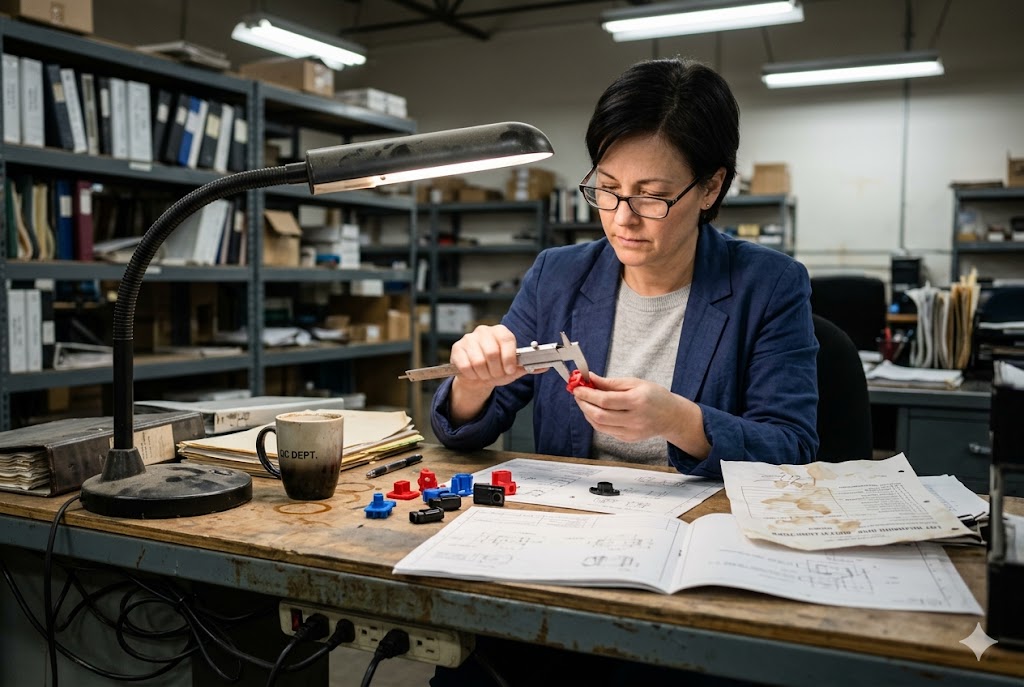
Every week, our team fields calls from purchasing managers who just received a batch of parts that look right but measure wrong. Tolerances are off by a hair — and that hair is costing them a production stoppage.
Yes, capable Chinese injection molding suppliers can consistently hold tolerances of ±0.01–0.05 mm on mold-fixed critical features using precision CNC machining and Wire Cut EDM. However, achieving this requires the right resin, proper mold cooling design, qualified inspection equipment, and a clearly written technical drawing. Not every factory can do it, and not every part design will allow it.
So how do you tell the difference before you place an order? That is exactly what this article covers.
What Tolerance Levels Can Most Chinese Injection Molding Factories Consistently Achieve?
When our sourcing team evaluates a new factory, the first question we ask is not "what is your price" but "show us your T1 CMM report." The answer tells us almost everything about what they can actually hold.
Most capable Chinese injection molding factories can achieve ±0.05 mm on standard features and ±0.01–0.02 mm on small, mold-fixed critical dimensions. Semi-crystalline resins like PP, PA, and POM make tighter tolerances harder to hold. Amorphous resins like ABS and PC shrink more predictably and support tighter bands. Glass-filled materials introduce anisotropic shrinkage that widens real-world tolerance bands significantly.
What the Numbers Actually Mean in Practice
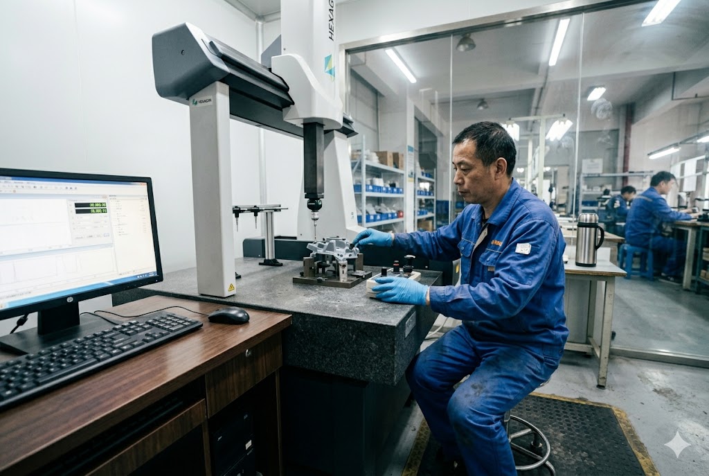
There is a gap between what a factory claims and what they can sustain across a full production run. Here is a honest breakdown of what is achievable by feature type and resin class.
| Feature Type | Achievable Tolerance (Amorphous Resin) | Achievable Tolerance (Semi-Crystalline Resin) |
|---|---|---|
| Small mold-fixed hole diameter | ±0.01–0.02 mm | ±0.03–0.05 mm |
| Wall thickness | ±0.05–0.10 mm | ±0.10–0.20 mm |
| Flatness (medium part) | ±0.10–0.20 mm | ±0.20–0.40 mm |
| Overall envelope (large part) | ±0.20–0.30 mm | ±0.30–0.60 mm |
| Thread engagement length | ±0.10 mm | ±0.15–0.25 mm |
These are not worst-case numbers. They reflect what a well-run factory with a properly designed mold can sustain across thousands of production shots — not just on hand-selected T1 samples.
The Role of Resin Choice
Material is the single biggest constraint. Amorphous resins like ABS, PC, and PS have a more uniform molecular structure. They cool at a predictable rate. Semi-crystalline resins like PP, PA66, POM, and PBT crystallize as they cool, and the crystallization rate is not uniform across a part. That introduces dimensional variation no mold or process adjustment can fully eliminate. Research confirms that semi-crystalline polymers such as PP and Nylon shrink 1.0% to 3.0%, while amorphous resins like ABS and PC shrink only 0.3% to 0.8% 1, making resin selection a critical upstream decision for any tight-tolerance application.
If your design requires tolerances tighter than ±0.10 mm on a medium-to-large part made from PP or PA, it is worth asking your supplier to run a Moldflow simulation before mold design approval. The simulation shows predicted shrinkage and warp deflection by zone. It catches problems before steel is cut. Autodesk's engineering blog notes that crystalline and semi-crystalline materials can shrink 2–5 times more than amorphous materials 2 due to the volume reduction that occurs during crystal packing — a physics constraint that mold tuning cannot eliminate.
The International Standard to Cite
Most disputes between importers and Chinese suppliers happen because the drawing says "±0.05 mm" with no reference standard. The supplier interprets it differently. The importer expected something else.
The correct approach is to cite ISO 20457-1:2018 in your purchase order and on your drawing. Advanced EMC Technologies explains that this standard defines three categories of tolerance classes based on increasing levels of precision 3, covering Standard, Medium, and Fine classes. Citing a specific class removes ambiguity and gives you a shared reference point for disputes.
| ISO 20457-1 Tolerance Class | Typical Use Case | Tightness Level |
|---|---|---|
| Class 1 | General-purpose parts, loose fits | Standard |
| Class 2 | Functional parts requiring moderate precision | Medium |
| Class 3 | High-precision parts, tight mating features | Fine |
If you write a raw dimensional callout with no standard reference, a Chinese supplier will default to what they consider "normal." That may not match your expectation.
Multi-Cavity Molds: The Problem No One Mentions
A single-cavity inspection can hide a serious quality problem. When a mold has four, eight, or sixteen cavities, each cavity has slightly different dimensions due to machining tolerances in the tooling itself. A supplier who inspects only one cavity — or who reports aggregate measurements — may be showing you best-case data.
For high-precision parts, require per-cavity CMM data from the T1 sample run. Contractually specify this before tooling begins. If all sixteen cavities pass, you have real confidence. If only twelve pass, you know before production release, not after.
How Do I Verify That a Chinese Injection Molding Supplier Can Hold the Tight Tolerances My Parts Require?
We have audited dozens of factories across Guangdong, Zhejiang, and Vietnam. The factories that can genuinely hold tight tolerances all have one thing in common: they welcome scrutiny. They do not get defensive when you ask for data.
To verify that a Chinese injection molding supplier can hold your required tolerances, ask for three things before placing an order: a First Article Inspection report with actual CMM measurement data, a Cpk report showing process capability index of at least 1.33 on critical dimensions, and a list of calibrated inspection equipment with calibration certificates. Suppliers who cannot provide all three should not be trusted with precision parts.

The Three Documents to Request Before You Commit
Most suppliers will send you a sample. Samples are not enough. A sample tells you what one part from one shot looks like on the day it was made. It tells you nothing about what the 5,000th part looks like six months from now.
These three documents tell you what you actually need to know:
First Article Inspection (FAI) Report
An FAI report documents the dimensional measurements of the first production parts against every callout on the drawing. It should show actual measured values, not just a pass/fail tick. It should be generated by CMM, not by a technician with a caliper.
Cpk Report
Cpk is the process capability index. It measures whether a process can consistently produce parts within a tolerance band. According to Six Sigma quality authorities, a Cpk of 1.33 represents the minimum acceptable capability for most manufacturing processes, corresponding to 4-sigma performance with approximately 63 defects per million opportunities 4. A Cpk of 1.67 or higher gives you even greater confidence.
A supplier who only shows you sample parts and not Cpk data is telling you something important: they are not running statistical process control.
| Cpk Value | What It Means | Acceptable? |
|---|---|---|
| Below 1.00 | Process is not capable; frequent rejects expected | No |
| 1.00–1.33 | Marginally capable; some defects likely | Marginal |
| 1.33–1.67 | Capable; suitable for most precision applications | Yes |
| Above 1.67 | Highly capable; suitable for tight-tolerance applications | Yes, preferred |
Calibration Certificates
Equipment that is not calibrated gives you numbers that feel precise but are not. Ask for the calibration certificate for every CMM, optical comparator, and profile projector the factory uses. Calibration intervals should be annual at minimum. If a factory cannot produce a calibration certificate, the measurement data it gives you is not reliable.
What to Ask During a Factory Audit
When our team visits a factory on behalf of a client, we walk the quality room before we walk the production floor. Here is a short checklist:
- Does the factory own a CMM? What model? When was it last calibrated?
- Can they show a live CMM measurement run on a part similar to yours?
- Do they have a temperature-controlled measurement room? (Required for sub-±0.05 mm work)
- Can they run Moldflow simulation in-house or do they outsource it?
- How do they handle cavity-to-cavity variation in multi-cavity molds?
A factory that answers all of these questions confidently and with documentation is worth serious consideration.
The Conditioning Protocol Problem
This is a detail that causes more disputes than almost anything else. Post-mold shrinkage continues for hours after a plastic part is ejected. The same part measured immediately after ejection and measured again after 24 hours of ambient conditioning can show dimensional differences that move a borderline part from pass to fail.
If your drawing does not specify a conditioning protocol — how long parts are stabilized at what temperature before measurement — your supplier and your incoming inspection team may measure the same parts at different times and get different results. Both measurements can be correct. The dispute happens because the protocol was never defined.
Write the conditioning protocol into the acceptance criteria before tooling begins.
What Inspection Equipment Should a Chinese Factory Have to Guarantee Dimensional Accuracy of Injection-Molded Parts?
When we qualify a new supplier for a precision parts project, the quality room inspection comes before the production floor tour. Equipment tells you more than promises.
A qualified Chinese injection molding factory handling tight-tolerance parts should own at minimum a CMM for 3D dimensional verification, an optical comparator or profile projector for 2D profile inspection, a mold temperature controller, and calibrated hand gauges. Factories working to tolerances below ±0.05 mm must also have a temperature-controlled measurement room and documented calibration schedules for all instruments.
The Equipment That Actually Matters
A factory can own a hundred gauges. What matters is whether those gauges are calibrated, used correctly, and used at the right stage of production.
Here is a practical breakdown of the key equipment categories:
Coordinate Measuring Machine (CMM)
CMM is the gold standard for 3D dimensional inspection. Industry guides confirm that a CMM measures actual coordinates of part surfaces against the nominal CAD model, enabling evaluation of geometric tolerances such as flatness, roundness, straightness, and positional accuracy 5. A factory without a CMM cannot reliably verify complex 3D geometry.
Ask the supplier which CMM brand and model they own. Leading brands in Chinese factories include Hexagon, Zeiss, and Renishaw. Ask when it was last calibrated and request the certificate. Modern injection molding quality control programs 6 increasingly combine CMM data with 3D scanning and statistical process control to detect dimensional drift before it causes a production escape.
Optical Comparator and Profile Projector
These tools project a magnified 2D shadow of a part onto a screen and compare it to an overlay template. They are fast and effective for verifying profiles, contours, and thread forms. They are not substitutes for CMM on 3D geometry, but they are valuable for 2D cross-section checks.
Mold Temperature Controller
Mold cavity temperature uniformity is as critical as cavity dimensions. Uneven cooling channels cause different sections of the part to solidify at different rates. This produces warpage and dimensional drift that inspection cannot correct after the fact. A mold temperature controller regulates the water or oil temperature in the cooling channels to maintain uniformity.
Require suppliers to provide the mold temperature controller specification and a cooling channel layout drawing as part of their DFM submission.
| Equipment | Primary Function | Required For Tolerances |
|---|---|---|
| CMM | 3D dimensional verification | ≤ ±0.10 mm |
| Optical Comparator | 2D profile and contour inspection | ≤ ±0.05 mm |
| Profile Projector | Thread, edge, and form inspection | ≤ ±0.05 mm |
| Mold Temperature Controller | Cooling channel temperature uniformity | ≤ ±0.10 mm |
| Calibrated Micrometers / Pin Gauges | In-process and incoming inspection | All levels |
| Temperature-Controlled Measurement Room | Stable ambient conditions for measurement | ≤ ±0.05 mm |
Why Post-Mold CNC Machining Is Sometimes the Right Answer
If your design genuinely requires tolerances below ±0.02 mm on a plastic part, there is a hard truth to face: injection molding alone may not be reliable enough.
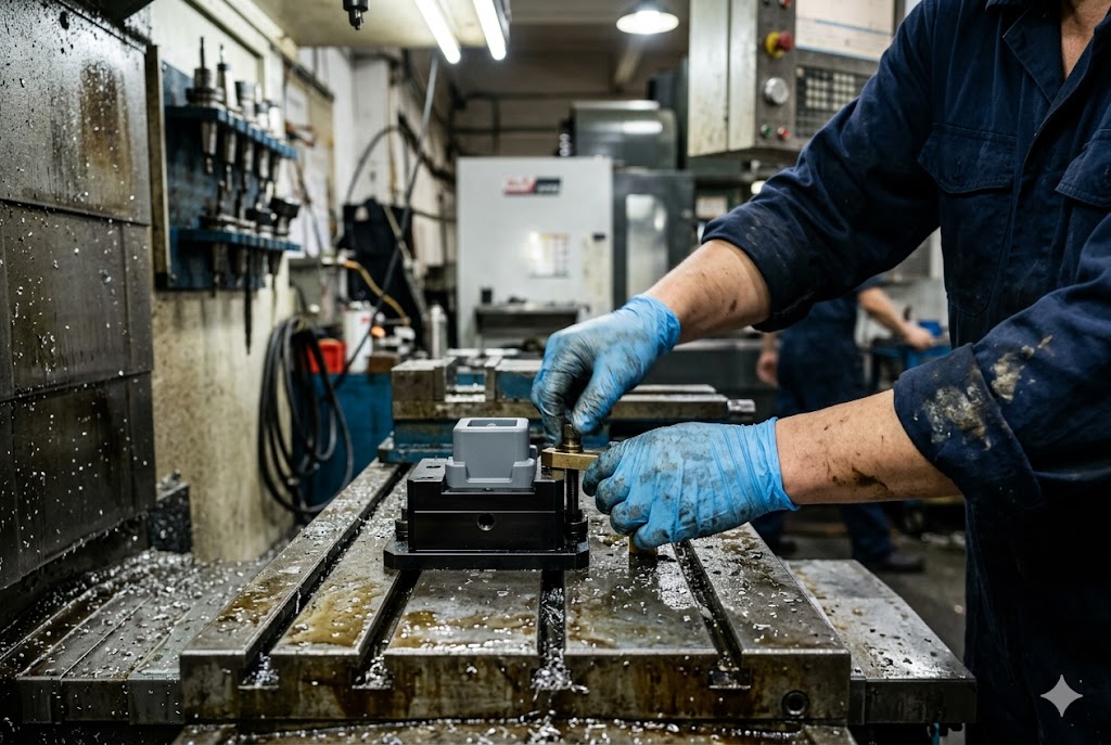
Post-mold shrinkage continues for hours after ejection. Thermal expansion in end-use environments can exceed the tolerance band. For sub-0.02 mm requirements on critical mating features, post-mold CNC machining of those specific features is a more reliable strategy than attempting to achieve it purely through molding process control. Wire Cut EDM 7 is particularly well-suited to this correction step, as it can achieve tolerances of ±0.0002 inches (approximately ±0.005 mm) without imposing mechanical stress on the workpiece, making it ideal for precision mold cavity work and post-mold feature refinement.
This is not a failure of Chinese manufacturing. It is a physics constraint of the process. Good suppliers will tell you this upfront. Be cautious of suppliers who promise sub-0.02 mm from the mold alone without discussing this limitation. Xometry's engineering resource library explains how Wire Cut EDM and sinker EDM are both widely used in injection mold toolmaking 8, with each serving a different function: Wire Cut EDM for through-cuts and complex profiles, sinker EDM for deep cavity features that conventional machining cannot reach.
How Do I Document My Tolerance Requirements Clearly in a Technical Drawing to Avoid Disputes With Chinese Suppliers?
After years of helping clients manage supplier disputes, most of the arguments we have seen could have been prevented by one thing: a better drawing. Not a more complex drawing. A clearer one.
To avoid tolerance disputes with Chinese injection molding suppliers, your technical drawing must explicitly cite ISO 20457-1:2018 with a specified tolerance class, define a dimensional conditioning protocol, use GD&T callouts for critical features, and include a separate critical-to-quality feature list in the drawing notes. Without these elements, your supplier will fill in ambiguity with their own defaults.

The Four Elements Every Precision Drawing Must Include
1. Standard Reference
Write "Per ISO 20457-1:2018, Tolerance Class [X]" in the drawing title block. This single line eliminates the single most common source of supplier-importer disagreement on what tolerance band is "normal."
2. Conditioning Protocol
Write the conditioning protocol directly in the drawing notes. Example: "Parts shall be conditioned at 23°C ±2°C for a minimum of 24 hours prior to dimensional inspection." This gives both you and your supplier a shared reference point for measurement.
3. GD&T for Critical Features
Raw dimensional callouts like "10.00 ±0.02 mm" are not always sufficient for complex geometry. GD&T (Geometric Dimensioning and Tolerancing) 9 communicates flatness, perpendicularity, true position, and profile tolerances in a standardized symbolic language that is internationally understood, providing a complete picture of how a part must behave geometrically — not just how large or small a feature is allowed to be. For precision mating features, GD&T removes the interpretation that causes disputes.
4. Critical-to-Quality Feature List
Add a table in the drawing notes that lists every CTQ feature by dimension number, the required tolerance, the required inspection method (CMM, optical comparator, etc.), and the required sample size. This tells the supplier exactly where to focus their inspection effort and what data you expect in the FAI report.
What Happens When Drawings Are Ambiguous
When a drawing is unclear, a Chinese supplier does not call you to ask. They make a judgment call. That judgment call is based on what is normal for them, not what is required by your application.
Common ambiguity problems include:
- No tolerance standard cited; supplier defaults to their own internal standard
- Flatness callout present but no specification of which datum it references
- No mention of conditioning protocol; supplier measures parts hot off the mold
- No CTQ feature list; supplier inspects the easy dimensions, not the critical ones
- No inspection method specified; supplier uses a caliper where a CMM is required
Each of these gaps is a potential dispute waiting to happen after delivery. The GD&T Basics resource 10 illustrates this problem clearly: a drawing that specifies only thickness tolerance cannot prevent a wavy or warped surface from passing inspection, because the thickness can be measured at individual points that each pass individually while the overall surface fails functionally.
Moldflow Simulation as a Drawing Review Tool
Before your mold is cut, ask your supplier to run a Moldflow simulation and provide the report. A Moldflow report shows predicted shrinkage by zone, warp deflection, fill pressure, and gate position effects. It tells you whether your current drawing's tolerance callouts are achievable given the resin and part geometry.
If the simulation shows that predicted shrinkage in a certain zone will produce 0.15 mm of warp on a feature where you have called ±0.05 mm, you have a problem — and you know about it before you have spent money on tooling. Suppliers who run Moldflow before cutting steel catch tolerance-threatening issues early. Require it as a condition of mold design approval.
Conclusion
Chinese injection molding suppliers can handle high-precision tolerances — but only if you choose the right factory, specify requirements clearly, and verify capability with real data before production begins. Do those three things and you protect your supply chain.
Footnotes
1. Detailed breakdown of shrinkage rates by resin type and how post-mold shrinkage affects dimensional stability over 24–48 hours. ↩︎
2. Autodesk's engineering guide on how crystallization behavior causes semi-crystalline materials to shrink 2–5× more than amorphous resins. ↩︎
3. Explains ISO 20457-1:2018's three tolerance classes and how they apply to injection-molded plastic part acceptance criteria. ↩︎
4. Comprehensive definition of Cpk, including why 1.33 is the accepted minimum and how it relates to sigma levels and defect rates. ↩︎
5. Guide to CMM inspection covering 3D measurement principles, injection mold qualification, and how CMM data connects to process adjustment. ↩︎
6. Overview of advanced injection molding quality control techniques including CMM, 3D scanning, and statistical process control integration. ↩︎
7. Explains Wire EDM capabilities, achievable tolerances (±0.0002 in), and why it is preferred for precision mold cavity and insert fabrication. ↩︎
8. Comparison of Wire Cut EDM and sinker EDM in injection mold toolmaking, including which features each process handles best. ↩︎
9. Introduction to GD&T symbols, feature control frames, and how they communicate design intent beyond simple plus/minus tolerancing. ↩︎
10. Foundational explanation of GD&T origins and how flatness callouts prevent parts from passing dimension checks while failing functionally. ↩︎



