 Skip to main content Skip to footer
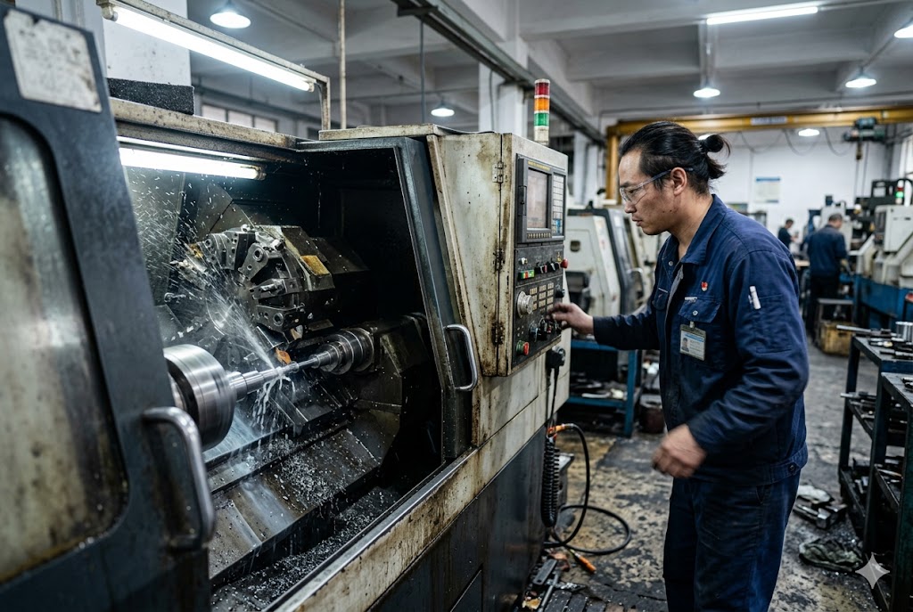
Every week, our sourcing team fields the same question from buyers in North America: can a Chinese Swiss shop actually handle mill-turn, or do parts need a second machine after turning? We hear it because the stakes are real — a missed mill-turn capability means re-chucking, angular error, and blown tolerances.
Yes, Chinese Swiss CNC factories comprehensively offer combined turning and milling capability. The majority of professionally equipped shops running Citizen, Tsugami, Star, or Tornos machines include live tooling, C-axis indexing, Y-axis off-center positioning, and sub-spindle backworking as baseline configurations, enabling complete mill-turn parts to drop finished in a single cycle.
This article breaks down what mill-turn actually means on a Swiss lathe, which part features require it, and how to communicate those features clearly on your drawing so you get an accurate quote the first time.
What Features on My Part Require Mill-Turn Capability Instead of Pure Swiss Turning?
When we review customer drawings before sending them to our supplier network, certain features immediately signal that a standard Swiss lathe is not enough — and missing that distinction early leads to expensive surprises later.
A part requires mill-turn capability when it includes any of the following: radial cross-holes or cross-tapped holes in a shaft, hex or polygon flats for wrench engagement, keyways or axial slots, off-center parallel features such as oblong holes, or face-milled pockets on either end of the part.
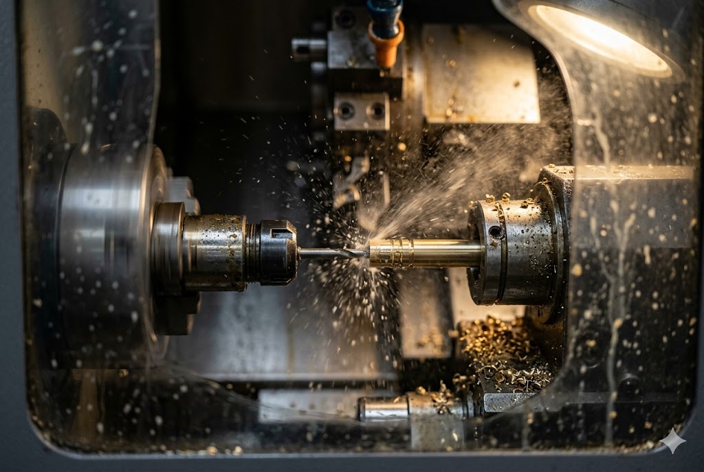
Turned Features vs. Mill-Turn Features
It helps to draw a hard line between what a pure Swiss lathe handles and what it cannot.
| Feature Type | Pure Swiss Turning | Requires Mill-Turn |
|---|---|---|
| OD turning, boring, grooving | ✔ | — |
| Axial face threading | ✔ | — |
| Radial cross-hole (through shaft) | ✗ | ✔ |
| Radial cross-tap (set-screw hole) | ✗ | ✔ |
| Hex flats / wrench flats | ✗ | ✔ |
| Keyway slot | ✗ | ✔ |
| Off-center parallel bore | ✗ | ✔ |
| Face pocket (milled recess) | ✗ | ✔ |
| Thread whirling (bone screw profile) | ✗ | ✔ |
Pure Swiss turning is fast and precise, but it can only cut features that are symmetric around the part centerline. The moment your design needs a feature at a specific angular location — a hole drilled 90° to the bore axis, a flat milled at a set distance from center — the machine must be able to hold the spindle at a commanded angle and drive a rotating tool independent of the part. That is exactly what live tooling plus C-axis indexing 1 provides.
The Three Capabilities That Define Real Mill-Turn
Not all Swiss lathes with live tooling are equal. There are three hardware capabilities that must all be present for a machine to handle the full range of mill-turn work:
Live tooling means the tool station has its own motorized spindle, completely independent of the workpiece spindle. It can drive end mills, drills, and taps at their own speed and feed. Without this, the tool has no way to rotate while the workpiece is stationary.
C-axis provides programmable angular indexing of the main spindle in 0.001-degree increments. This is how the machine positions a cross-hole at exactly 45° from a keyway, or spaces six set-screw holes evenly around a shaft. Many Swiss lathes 2 have C-axis capability through the main spindle drive motor.
Y-axis is the capability most commonly missing on lower-end machines. X and Z axes plus C-axis can reach most radial features, but any feature that is offset from the centerline — a flat milled at a specific distance from center, an oblong slot, a bore not on the OD surface — requires true Y-axis linear travel. Shops that have invested in Y-axis-equipped machines (often described as 7-axis or higher) can handle a much broader range of prismatic-on-cylindrical geometries.
Part Families That Almost Always Need Mill-Turn
From our factory visits and order history, these part families virtually always require mill-turn capability:
- Fluid fittings and valve bodies — cross-drilled ports, hex wrench flats, face O-ring grooves
- Shaft assemblies with set-screw collars — radial tapped holes at defined angular positions
- Electrical connector bodies — axial face slots for index keys, radial cross-holes for locking pins
- Orthopedic bone screws — thread whirling plus hex or Torx drive recess milled in the head, cannulated bore
- RF coaxial connector bodies — OD thread plus radial cross-holes with tight angular relationship to thread start
How Does Live Tooling on a Swiss-Type Lathe Enable Milling, Drilling, and Cross-Hole Operations?
Our engineers spend a lot of time on supplier factory floors watching machines run before we approve them for a customer's program. Understanding exactly how live tooling works on a Swiss lathe helps you ask the right questions when vetting a factory.
Live tooling on a Swiss lathe uses independently motorized tool stations on the gang slide or turret to drive rotating end mills, drills, and taps at their own speed while the workpiece spindle is held stationary by the C-axis. This enables milling, cross-drilling, cross-tapping, and polygon milling without removing the part from the machine.
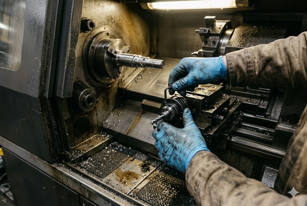
How the Machine Sequence Works
A Swiss lathe in mill-turn mode follows a defined sequence. It is worth understanding each step because it directly explains why parts come out more accurately than they would on two separate machines.
First, the main spindle completes the turning cycle — OD diameter, grooving, threading — while the guide bushing 3 holds the bar stock close to the tool tip. This proximity is what allows Swiss lathes to hold tight tolerances on long, slender parts.
Next, the C-axis motor locks the spindle at a commanded angular position. The position is held with servo feedback to 0.001-degree resolution. The part is now frozen at the exact angle where the milled feature must land.
Then, the live tool station activates. Its own spindle motor drives the end mill or drill at programmed speed. The X and Z axes (or X, Y, and Z on a full Y-axis machine) position the rotating tool against the stationary part. The cut proceeds exactly as it would on a vertical machining center, except the workpiece is clamped to the collet instead of a vise.
Finally, the C-axis unlocks, the spindle indexes to the next angular position if needed, and the cycle repeats until all mill-turn features are complete.
Machine Configurations Deployed in Chinese Shops
Chinese Swiss shops serving export markets typically run one of four major imported machine platforms, each with a distinct approach to live tooling:
| Machine Platform | Live Tool RPM | C-Axis | Y-Axis | Sub-Spindle |
|---|---|---|---|---|
| Citizen Cincom L-series | Up to 10,000 RPM | ✔ | ✔ (select models) | ✔ |
| Tsugami B-series | Up to 12,000 RPM | ✔ | ✔ | ✔ |
| Star SR-series | Up to 8,000 RPM | ✔ | ✔ (select models) | ✔ |
| Domestic (JSWAY, TAIKE) | 5,000–6,000 RPM | ✔ | Limited | Some models |
The live tool RPM ceiling matters for surface finish on small-diameter end mills. To maintain cutting speed on a 2mm end mill, you need high spindle RPM. Citizen and Tsugami platforms comfortably reach the 8,000–12,000 RPM range that keeps surface footage in spec for fine milling operations. Domestic Chinese machines typically cap at 5,000–6,000 RPM, which can limit achievable milled surface finish on small features without secondary hand-finishing.
What Operations Run on Each Axis
Understanding which machine axis drives each operation helps when reviewing a supplier's capability statement:
Radial cross-drilling uses C-axis to hold the angular position and X-axis to feed the live drill into the part diameter.
Radial cross-tapping follows the same motion as cross-drilling. The live tool switches to a tap, and the machine synchronizes tool rotation with Z-axis feed to produce threads.
Keyway milling uses C-axis to lock the spindle and Z-axis to traverse a live end mill along the part length, cutting the keyway slot.
Hex and polygon milling uses synchronized rotation of both the C-axis and the live tool spindle to generate flat faces around the circumference. This is called polygon milling 4.
Face milling and face drilling are performed on the sub-spindle side after the part is parted off and transferred. The sub-spindle grips the finished end, and the rear-mounted live tools operate on the face, eliminating the need to rechuck the part for backworking.
Does Adding Milling Operations to a Swiss-Turned Part Significantly Increase Cost and Lead Time?
Buyers often ask us to estimate the cost delta before they commit to a mill-turn design. The honest answer is nuanced, and understanding where cost comes from helps you make smarter design decisions.
Adding milling operations to a Swiss-turned part does increase unit cost, but the increase is often smaller than buyers expect because mill-turn consolidates work into one machine cycle. Eliminating a secondary CNC setup removes fixture cost, inter-operation inspection, and the lead time buffer of work-in-process inventory sitting between two machines — sometimes days of queue time disappear.

Where Cost Increases Come From
Mill-turn operations add cost through two main channels: cycle time and tooling.
Every live tool operation extends the cycle. A cross-drill might add 8–20 seconds per hole depending on diameter and depth. A keyway pass might add 15–40 seconds depending on length and material. These seconds accumulate, and on a Swiss lathe billing at a certain machine rate per hour, longer cycles mean higher unit cost.
Tooling cost is the second channel. Live tools wear faster than turning inserts on some materials, especially stainless steel and titanium. Shops that specialize in mill-turn work 5 typically have optimized tool paths and proven tooling programs that minimize waste, but first-article runs on a new part will include some tooling development cost.
Where Cost Is Offset
The cost increases above are often partially or fully offset by consolidation savings:
| Cost Item | Two-Machine Workflow | Mill-Turn Workflow |
|---|---|---|
| Secondary fixture | Required — adds cost | Eliminated |
| Inter-operation WIP buffer | 1–3 days queue | Eliminated |
| Inter-operation inspection | Required at each handoff | Removed from flow |
| Re-chucking angular error | Present — may cause rejects | Eliminated |
| Setup changeover (2nd machine) | Full setup required | None |
The quality benefit is not just a soft argument. When a cross-hole must land at a specific angular position relative to a thread start, re-chucking the part on a second machine introduces angular scatter. If that tolerance is tight — as it often is in medical and RF connector applications — you pay for 100% inspection or accept a reject rate. Mill-turn eliminates the scatter entirely. That is a hard cost reduction.
Lead Time Impact
Lead time typically improves with mill-turn consolidation when a part previously moved between two machines with queue time in between. Our experience booking orders through Chinese Swiss shops shows that parts requiring a secondary VMC operation often carry two to four extra days of lead time purely from machine scheduling and WIP queue. Mill-turn removes that buffer.
The one scenario where lead time can increase is when a shop's mill-turn machines are running at high utilization while their plain turning machines have open capacity. In that case, routing a simple turned part to a mill-turn machine occupies a more expensive, busier asset. A good factory will route parts intelligently to match machine capability to part requirement. Setting up a Swiss lathe correctly 6 for a new program also affects whether lead time stays on target.
How Do I Indicate Milling Features on My Drawing So the Factory Quotes Mill-Turn Correctly?
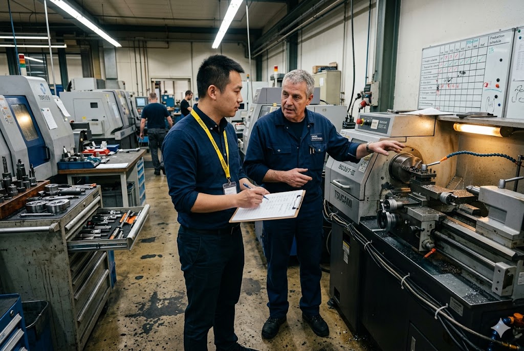
After years of reviewing drawings before they go to suppliers, we see the same quoting errors repeat. Most of them trace back to drawings that do not clearly communicate which features are milled, what tolerances apply, and what the angular relationships are between features.
To ensure a factory quotes mill-turn correctly, your drawing must explicitly call out every milled feature with its tool approach direction, angular position referenced to a datum, toleranced depth and diameter, and surface finish requirement. Do not assume the factory will infer mill-turn need from geometry alone — state it, dimension it, and datum it.
The Most Common Drawing Errors That Cause Misquotes
From our quoting experience, these are the top reasons a drawing produces an incorrect or incomplete mill-turn quote:
Missing angular datum. The cross-hole is shown in a side view, but there is no reference angle from a datum feature — typically a flat, a keyway, or a thread start. Without this, the shop does not know what the angular position means and may not quote the C-axis indexing required to hold it.
No surface finish callout on milled surfaces. Turned surfaces and milled surfaces on the same part often have different finish requirements. If the drawing carries a single block tolerance finish for all surfaces, the shop may not budget for the additional milling passes or grinding needed on specific faces.
Depth of cross-hole not toleranced. A cross-hole shown as a through-hole is clear. But a blind cross-hole or a partial-depth cross-tap without a positional tolerance leaves the shop guessing, and conservative assumptions inflate the quote.
Omitting the sub-spindle requirement. If features on both ends of the part require machining, the drawing needs to make that explicit. If a buyer does not indicate that the back face requires face drilling, the factory may quote a single-spindle machine and exclude the sub-spindle operation. The sub-spindle's C-axis resolution 7 — typically 360,000 radial positions, or 0.001-degree increments — is what controls angular relationship between front and back features, and the drawing must establish what that relationship must be.
How to Dimension Mill-Turn Features Correctly
| Feature | Required Callout | Common Omission |
|---|---|---|
| Radial cross-hole | Diameter, depth, angular position from datum A (thread or flat), positional tolerance | Angular datum missing |
| Cross-tap | Thread spec (M3×0.5), depth, angular position from datum | Depth tolerance missing |
| Keyway | Width, depth, length, position from face datum, fit class | Fit class missing |
| Hex flat | Across-flat dimension, tolerance, angular reference | Angular reference to bore missing |
| Face pocket | Width, depth, corner radius, surface finish | Corner radius not specified |
| Off-center bore | Center offset from part axis, diameter, depth, positional tolerance | Offset tolerance missing |
Recommended Drawing Notes for Mill-Turn Parts
Adding a short general note block to your title sheet saves significant back-and-forth with the factory:
-
State which operations require single-setup completion: "All radial cross-holes and face features to be completed in single clamping. No re-chucking permitted between turning and milling operations."
-
Identify the primary angular datum explicitly: "Datum A = thread start of M10×1.0 external thread. All angular dimensions reference Datum A."
-
Call out sub-spindle requirement if applicable: "Back face features (see Detail B) require sub-spindle machining. Angular relationship between front and back features held to ±0.5°."
These notes eliminate ambiguity. A quoting engineer reading a drawing with these notes can immediately confirm whether their machines meet the requirement and price accordingly. A drawing without these notes invites assumptions — and assumptions in machining quotations almost always mean scope gaps that become change orders. Understanding G-code and programming structure 8 for Swiss lathes can also help buyers anticipate how factories structure their setups and price operations.
How We Verify Factory Mill-Turn Capability Before Committing Your Order
When our team qualifies a factory for a mill-turn program, we look at three things beyond the machine spec sheet. First, we ask to see a sample part or inspection report from a comparable job — same diameter range, similar feature mix. Second, we review the CMM report 9 format: does the factory measure angular position of cross-holes relative to a primary datum, or do they only measure hole diameter? A shop that does not measure angular position is not controlling it. Third, we inspect live tool condition on the machines proposed for the job. Worn live tool spindle bearings cause chatter on milled features even when the turning surfaces come out clean.
The volumetric accuracy of coordinate metrology equipment 10 used at the factory — and whether that equipment is properly calibrated and temperature-controlled — directly determines how reliably the shop can verify angular positions and positional tolerances on mill-turn parts.
Conclusion
Chinese Swiss CNC factories running major imported machine platforms offer genuine mill-turn capability as standard. The key is knowing which features trigger the requirement, how to read a factory's true capability, and how to write drawings that leave no room for misinterpretation.
Footnotes
1. SME article on live tooling, C-axis, and Y-axis enabling single-setup mill-turn on Swiss lathes for medical parts. ↩︎
2. Nomura DS guide covering Swiss machining fundamentals: guide bushing, sliding headstock, multi-axis, and live tooling. ↩︎
3. Tooling U-SME course covering the guide bushing as the defining characteristic of Swiss-type lathes. ↩︎
4. SME article on advanced Swiss lathe capabilities including Y2-axis, B-axis, and polygon milling. ↩︎
5. SME article on current Swiss machine advances including tool-life optimization and multi-axis configurations. ↩︎
6. Nomura DS guide to Swiss lathe setup, process control, and first-part validation for high-volume production. ↩︎
7. SME product introduction detailing C-axis resolution of 360,000 positions (0.001°) and dual-Y-axis sub-spindle capability. ↩︎
8. Nomura DS guide to Swiss lathe G-code programming, multi-channel synchronization, and first-part validation. ↩︎
9. GD&T Basics primer on CMM inspection, 3D point-cloud measurement, and angular feature verification. ↩︎
10. Hexagon introduction to coordinate metrology covering CMM error sources, volumetric error compensation, and calibration. ↩︎



