 Skip to main content Skip to footer
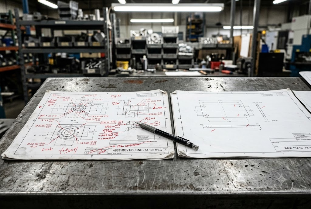
Every week, our team reviews drawings from buyers who over-specify some things and under-specify others. Both mistakes cost money. The question of how much process detail to put on a drawing is one we deal with constantly.
In most cases, you do not need to specify the machining process when sourcing CNC parts from China. Define the outcome — tolerances, surface finish Ra values, and GD&T — and let the supplier choose the process. However, for features requiring EDM, grinding, honing, or a fixed heat treatment sequence, you must specify the process explicitly or risk receiving non-conforming parts.
If you get this balance wrong, you either constrain a capable supplier unnecessarily or give an under-equipped one too much freedom. Here is how to find the right line.
Should I Define CNC Milling vs. Turning?
When we review drawings from new clients, the most common mistake we see is not under-specifying — it is over-specifying the wrong things. Buyers lock in a process that made sense on their end but does not fit the supplier's equipment.
For standard geometry, do not specify milling vs. turning. Define the outcome through tolerances, surface finish, and GD&T. Tell a supplier to use a 3-axis mill when a 5-axis approach suits the part better, and you add setups, reduce accuracy, and increase cost — all at the same time.
What Happens When You Over-Specify the Process
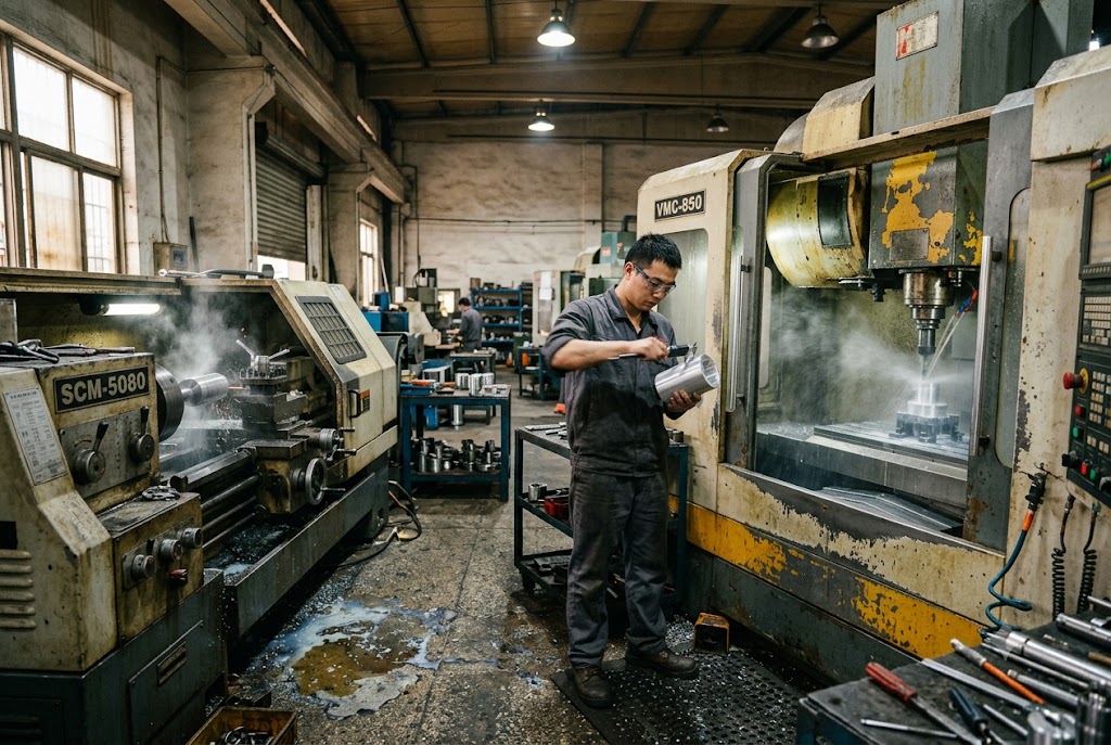
When a buyer writes "machine using 3-axis milling with 6 mm end mill at 1500 RPM" on a drawing note, two things happen. A capable supplier ignores the note and machines it correctly using their own process knowledge. A less experienced supplier follows the note literally — on a different machine, with different tooling, cutting a different material batch — and produces incorrect results.
Neither outcome is good. The capable supplier ignores your instruction and you have no idea. The less capable supplier follows it blindly and delivers a bad part.
The correct approach is to define what the part must do, not how to make it.
What to Put on the Drawing Instead
| What to Specify | What Not to Specify |
|---|---|
| Dimensional tolerances (e.g., ±0.01 mm) | Cutting tool diameter or type |
| Surface finish Ra value (e.g., Ra 0.8 µm) 1 | Spindle speed or feed rate |
| GD&T callouts 2 (flatness, cylindricity, etc.) | Number of setups |
| Material and hardness | Machine model or axis count |
| Thread class and fit (e.g., 6H) | Fixture method |
This table shows what belongs on a drawing and what belongs in the supplier's process plan — not yours.
When Process Selection Affects Cost
A supplier choosing between 3-axis and 5-axis machining 3 will pick the method that suits their shop floor. If they have 5-axis capability, they will use it for complex geometry because it reduces setups and improves accuracy. If you force 3-axis by drawing note, you add cost without adding value.
The same applies to turning. A turned bore with a tight tolerance is faster and cheaper to produce on a lathe than on a machining center. Specifying "milled bore" when the geometry is purely cylindrical forces the supplier into a suboptimal process.
The One Exception: Features That Cannot Be Made by Standard CNC
There are features that standard CNC tooling simply cannot produce. Internal sharp corners with a radius below the smallest available end mill. Deep narrow slots. Hardened steel features. Complex freeform surfaces. For these, you must specify the required process — EDM, wire EDM, 4 grinding, or honing — or the supplier will attempt the feature with standard tooling, discover the limitation mid-job, and either deliver a non-conforming part or request a costly engineering change.
The rule is simple: if the geometry physically cannot be achieved by standard CNC, say so on the drawing.
Can Suppliers Choose Processes Themselves?
From our experience managing production across multiple factories in China and Vietnam, suppliers are generally better at choosing their own process than buyers expect. The problem is not that they choose wrong. The problem is that there are specific cases where no default exists — and the supplier will fill the gap with whatever is cheapest or fastest.
Suppliers can and should choose their own machining process for standard features. However, for heat treatment sequence, secondary operations like passivation or stress relief, and features with functional surface requirements, the supplier has no reliable default. You must specify these explicitly or they will be skipped or done incorrectly.

Heat Treatment: The Most Commonly Mishandled Specification
Heat treatment sequence 5 is the single area where supplier defaults cause the most quality failures in our experience. The correct sequence for most parts is: rough machine → heat treat → finish machine. This removes distortion introduced by heat treatment and restores datums.
A supplier without a sequence note on the drawing will heat treat either before machining or after final machining. Both are wrong for most cases. Heat treating before machining means the final surface was never machined after distortion occurred. Heat treating after final machining means distortion moves critical features out of tolerance.
How to Write a Complete Heat Treatment Callout
"Harden" is not a specification. It gives the supplier five degrees of freedom: process, depth, hardness level, region, and verification method. A professional callout looks like this:
| Element | Example Callout |
|---|---|
| Process | Induction harden |
| Hardness range | 55–58 HRC |
| Case depth | 1.5–2.0 mm ECD |
| Affected region | "Bore surface B only" |
| Conformance requirement | Hardness certificate with each shipment |
Every one of these elements must appear on the drawing or in the purchase order. If any element is missing, the supplier fills the gap with their own judgment — and that judgment varies between runs, between production personnel, and between factories.
Secondary Operations: What Gets Skipped When Not Specified
Deburring, passivation per ASTM A967, 6 stress relief, and thread chasing are routinely omitted by suppliers when not explicitly called out. These operations add cost and time with no visible effect on part geometry. A stainless steel part that required ASTM A967 passivation will look identical to one that was not passivated. It will fail corrosion testing at incoming inspection. But it will pass every visual check.
The same applies to thread chasing after plating or coating. If not specified, it will not be done. The buyer discovers the issue when the assembly line finds threads that will not accept a fastener.
List all secondary operations as required line items in both the drawing notes and the purchase order. Do not assume they are standard practice.
Surface Lay and Functional Properties
Some features require a specific machining method not because of a dimension, but because of a functional property. Cross-hatch honing in cylinder bores 7 retains lubricant in a way that ground or reamed bores do not. A bearing housing with a specific surface lay requirement must call out the lay direction using ISO 1302 symbols. 8
A supplier choosing between grinding and boring will produce geometrically identical results that behave differently in service. If the functional property matters, specify the process that produces it.
How Does Process Selection Affect Cost?
Buyers often think that specifying more controls cost. In practice, the opposite is usually true. Over-specification adds cost. Under-specification causes rework, which adds more cost. The lowest-cost outcome comes from letting capable suppliers choose their process while specifying exactly what the part must achieve.
Process selection directly affects cost through setup count, tooling constraints, and secondary operations. Allowing suppliers to optimize their process for standard features reduces cost. However, failing to specify required secondary operations — grinding, honing, passivation — creates hidden costs at inspection or in the field that far exceed the original savings.
Where Grinding Belongs in the Quote
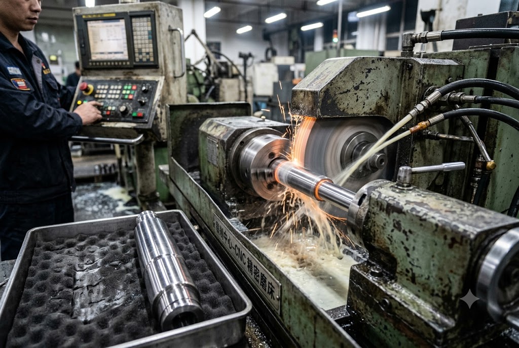
Grinding is required when a dimensional tolerance or surface finish is tighter than standard CNC milling or turning can reliably achieve. The thresholds are clear:
| Requirement | Standard CNC Capability | Grinding Required |
|---|---|---|
| Surface finish | Ra ≥ 0.8 µm | Ra < 0.8 µm on steel |
| Bore tolerance | ±0.01 mm and above | Below ±0.008 mm |
| Flatness on hardened surfaces | 0.05 mm and above | Below 0.02 mm |
When grinding is required but not specified, one of two things happens. A capable supplier adds the step without disclosing it in the quote, which causes a price dispute later. A less capable supplier skips it and delivers parts that pass visual inspection but fail dimensional measurement.
Either way, you pay more than you planned — or you pay in rework and delays.
Setup Count and Its Impact on Price
Every time a part is refixtered, there is a risk of introducing datum shift. There is also a cost: the machine stops, an operator resets, and re-inspection may be required. A supplier given the freedom to choose their process will minimize setups where possible. A buyer who specifies "machine all faces on a 3-axis mill" may force three setups where a 5-axis approach would use one.
For buyers sourcing from China or Vietnam, this matters because setup time is priced into the quote. Reducing setups reduces price and improves geometric accuracy between features machined in the same setup.
Specifying Setup Sequence for Critical Datum Relationships
There is one area where buyers should specify the setup — not the tooling or cutting parameters, but the datum relationship within a setup. A note stating "machine Datum A surface in the same setup as bore B before any part refixtered" controls the geometric relationship that matters functionally. It does this without constraining the supplier's choice of tooling, fixturing method, or cutting strategy.
This is the correct level of process specification for a buyer who is not the machinist. You control what matters — the relationship between features — and leave everything else to the supplier.
Should I Request Process Explanations?
Many buyers skip this step entirely. They send a drawing, receive a quote, and place an order. The process the supplier plans to use is never discussed until something goes wrong. By then, correcting course is expensive.
You should request process explanations during the DFM review stage, not on the drawing. Ask the supplier to propose their machining process for critical features before production begins. Review and approve their process plan. This gives you visibility and veto rights without locking the drawing to a specific process that may be unavailable or inappropriate for a future supplier.
What DFM Review Should Cover
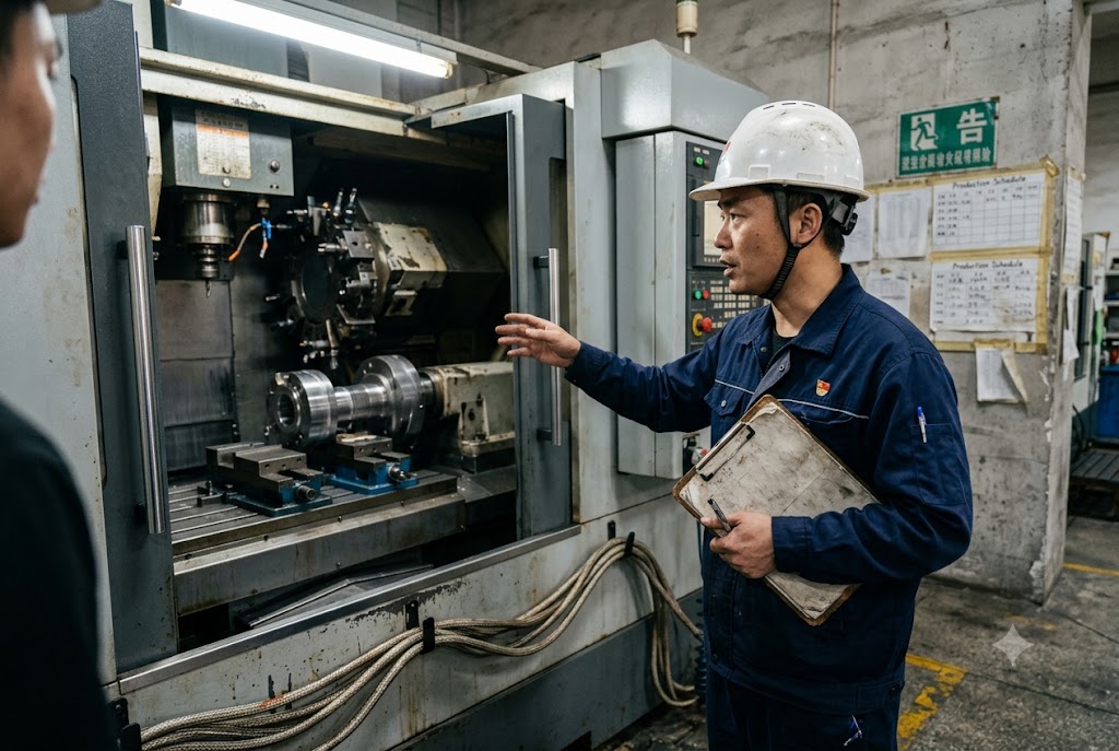
DFM — Design for Manufacturability 9 — review is the correct forum for process discussion. When a supplier receives a drawing and proposes how they will make the part, that proposal should include:
- How they will hold the part and how many setups are planned
- What process they intend for tight-tolerance features
- Whether any feature requires a non-standard operation (EDM, grinding, honing)
- The heat treatment sequence if heat treatment is required
- Any secondary operations they plan to include
This information should come back in writing before the first piece is cut. It does not need to be a formal document. An email with a clear statement of the supplier's intended process is sufficient.
Why the Drawing Is the Wrong Place for This Conversation
A drawing is a permanent, version-controlled document. A process note on a drawing becomes a constraint for every future supplier who quotes that part. If you specify a process that one supplier uses but another does not have, you either limit your supply base unnecessarily or force a costly drawing revision.
Process discussion belongs in the pre-production phase, not the drawing. The drawing defines what the part must be. The DFM review defines how this specific supplier, with their specific equipment, will make it.
What to Do When a Supplier Cannot Explain Their Process
If a supplier cannot explain how they plan to machine a critical feature, that is a signal. It does not always mean they cannot make the part. It may mean their sales representative is not technical enough to bridge the conversation. In our experience sourcing for clients across the US and Canada, this is a common issue — and it is one of the main reasons buyers lose confidence in Chinese suppliers.
Ask to speak with the engineer or process planner, not just the sales contact. A capable factory will have someone who can walk through the process at a technical level. If they cannot produce that person, proceed with caution.
Conclusion
Specify outcomes, not methods. Define tolerances, surface finish, heat treatment sequence, and secondary operations explicitly. Leave cutting parameters, tooling, and setup strategy to the supplier. Use DFM review to discuss process — not the drawing. A final check: verify your drawings include proper GD&T callouts per ASME Y14.5 10 — the universal language that bridges design intent and supplier execution across borders.
Footnotes
1. Guide to Ra surface roughness values and what each level means for CNC machining. ↩︎
2. Introduction to GD&T principles, symbols, and how they communicate design intent to manufacturers. ↩︎
3. Comparison of 3-axis and 5-axis CNC machining capabilities, cost tradeoffs, and when each is appropriate. ↩︎
4. Overview of electrical discharge machining (EDM): how it works, types, and when it replaces standard CNC. ↩︎
5. Complete guide to heat treatment sequencing for CNC parts, including distortion control and machining allowance planning. ↩︎
6. Explanation of ASTM A967 passivation for stainless steel: process methods and compliance testing requirements. ↩︎
7. How cross-hatch honing creates oil-retaining surface texture in cylinder bores that grinding cannot replicate. ↩︎
8. Reference guide to ISO 1302 surface texture symbols and how to correctly specify surface lay on engineering drawings. ↩︎
9. Overview of DFM principles for CNC machining and how pre-production review reduces cost and rework. ↩︎
10. Guide to GD&T fundamentals per ASME Y14.5, covering datums, feature control frames, and tolerance zones. ↩︎



