 Skip to main content Skip to footer
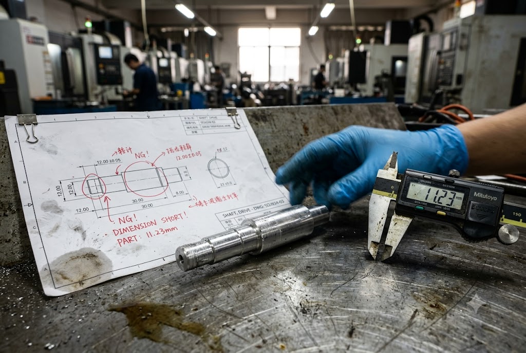
We see it happen more than once a year. A drawing lands on the shop floor, the machinist assumes millimeters, and the finished part is 25.4 times off on every dimension. The error is silent until inspection — and by then, material and time are already gone.
Unit confusion between inch-based US drawings and metric-based Chinese CNC shops is one of the most preventable causes of scrapped parts. Declaring the unit system in the title block, converting all dimensions to millimeters before sending, and confirming STEP file export units eliminates the vast majority of these errors before production starts.
The fixes are simple. But they require deliberate habits. Here is what you need to know.
Should I Always Use Metric Units?
Our team has reviewed hundreds of drawings sent by US clients. The single most common missing detail is a unit declaration. Chinese shops run entirely on the metric system, and a blank unit field means the machinist assumes millimeters — every time.
Yes, you should always use metric units when working with Chinese CNC suppliers. All Chinese CNC machines, calibrated gauges, and standard tooling are sized in millimeters. A drawing without a clear unit declaration will be machined in millimeters by default, which means an inch-based drawing will produce a part 25.4 times smaller than intended.

Why China Is a Metric-Only Environment
China adopted the metric system 1 as its national standard decades ago. Every CNC controller on the shop floor is set to millimeters. Every calibrated inspection instrument reads in millimeters. Standard drills, taps, and end mills are sold in metric sizes. There are no imperial alternatives stocked as default consumables.
This is not a preference. It is the infrastructure. When a drawing arrives in inches and nothing flags it, the shop does not switch systems. It reads the numbers and machines to those numbers — in millimeters.
What Happens When Units Are Assumed Wrong
The math is straightforward and brutal. One inch equals 25.4 millimeters. If a shaft is designed to 1.250 inches and the machinist reads 1.250 millimeters, the finished shaft is 96% smaller than intended. It will not fit any mating part. The entire production run is scrap.
The table below shows how common nominal dimensions shrink when inch values are misread as millimeters.
| Intended Dimension (inches) | Misread as (mm) | Actual Intended Value (mm) | Error Factor |
|---|---|---|---|
| 1.000 in | 1.000 mm | 25.400 mm | ×25.4 |
| 0.750 in | 0.750 mm | 19.050 mm | ×25.4 |
| 2.500 in | 2.500 mm | 63.500 mm | ×25.4 |
| 0.125 in | 0.125 mm | 3.175 mm | ×25.4 |
How to Declare Units Correctly
The unit declaration belongs in the title block 2 — the standard information panel printed in the bottom-right corner of every engineering drawing. Most title block templates include a field labeled "Units" or "Dimensions In." Fill it in. Every drawing. Every time.
Beyond the title block, add a general note near the drawing border that reads: "ALL DIMENSIONS IN MILLIMETERS UNLESS OTHERWISE NOTED." This note acts as a second line of defense for any shop floor worker who does not read title blocks carefully.
At the point of order placement, confirm the unit system verbally or in writing with your supplier contact. A one-line email — "All dimensions on attached drawings are in millimeters" — takes ten seconds and eliminates ambiguity.
Angular Units Matter Too
Most buyers focus on linear units and forget angles. Chinese CNC programmers use decimal degrees natively — for example, 23.258°. A US drawing that writes an angle as 23°15'30" (degrees-minutes-seconds) requires the machinist to convert before entering the value into the controller. The conversion is simple arithmetic, but it is one more opportunity for a transcription error, especially for shop floor staff reading an English-language drawing under time pressure.
Specify all angles as decimal degrees on any drawing destined for a Chinese supplier.
How Can I Prevent Inch/mm Conversion Errors?
When clients send us imperial drawings and ask us to forward them to Chinese factories, we always convert first. We have seen what happens when conversion is left to the shop floor — rounding eats tolerances quietly.
To prevent inch/mm conversion errors, convert all dimensions to millimeters yourself before sending the drawing to your Chinese supplier. Do not ask the supplier to convert. Every converted dimension should be rounded to the same number of decimal places as the original tolerance demands, and the converted tolerance must be checked to confirm it has not been silently widened by rounding.
The Rounding Problem Nobody Talks About
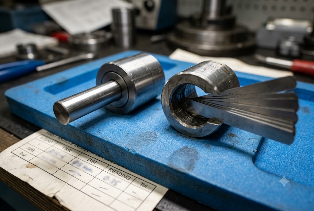
Converting 0.750 ±0.001 inch to millimeters gives 19.050 ±0.0254 mm. That tolerance — 0.0254 mm — does not round cleanly. A supplier who rounds it to ±0.025 mm has widened your tolerance by 1.6%. That sounds small. Across a drawing with 40 dimensioned features, these small errors accumulate. The part may pass every individual dimension check and still fail assembly because the cumulative deviation pushes a critical fit outside its acceptable range.
The table below shows how common imperial tolerances translate to metric and where rounding risk is highest.
| Imperial Tolerance | Exact Metric Equivalent | Rounded to 3 dp (mm) | Tolerance Change |
|---|---|---|---|
| ±0.001 in | ±0.0254 mm | ±0.025 mm | Widened by 1.6% |
| ±0.002 in | ±0.0508 mm | ±0.051 mm | Widened by 0.4% |
| ±0.005 in | ±0.127 mm | ±0.127 mm | No change |
| ±0.010 in | ±0.254 mm | ±0.254 mm | No change |
Tight tolerances — ±0.001 in and tighter — carry the highest rounding risk. These are exactly the tolerances that matter most for precision fits. Do not leave them to chance.
Surface Roughness: A Hidden Unit Trap
Surface roughness 3 is the most overlooked unit conversion problem in cross-border machining. The Ra value on a drawing looks like a plain number. But the unit behind it changes its meaning completely.
Ra 3.2 on a metric drawing means 3.2 µm (micrometers). That is a normal as-machined finish. Ra 32 on an imperial drawing means 32 µin (microinches), which converts to 0.813 µm — a precision finish that requires optimized cutting speeds, feeds, and potentially additional finishing operations.
A Chinese inspector who reads the numeral 32 from an imperial drawing and interprets it as 32 µm — 40 times coarser than intended — will accept surfaces that are far rougher than your design requires. This specific confusion between µm and µin accounts for a meaningful share of surface finish failures caught during pre-shipment inspection.
The fix: always add the unit abbreviation directly after the Ra value on the drawing. Write "Ra 32 µin" or "Ra 0.813 µm," never just "Ra 32."
Thread Callouts Are Not Universal
A thread callout of "5/16–18 UNC" is clear to any US machinist. It is a problem for a Chinese shop. Imperial taps are not standard consumables in China. If the supplier does not flag the issue, they will either substitute the nearest metric equivalent 4 (M8 × 1.25 is geometrically close but not interchangeable) or attempt to source imperial tooling without telling you.
Use unambiguous international notation wherever possible. "M8 × 1.25 – 6H" is readable by every CNC programmer in China. Where imperial threads are functionally required by your design, state it explicitly, confirm the supplier has the correct tooling before production starts, and request a sample thread gauge check on the first article.
Should I Standardize Drawing Formats?
Our engineers have found that drawing format mismatches cause more back-and-forth than almost any other technical issue. A drawing that follows ASME Y14.5 5 and a shop that works to GB/T standards are not automatically reading the same language, even when the dimensions are correct.
Yes, standardizing your drawing format for Chinese suppliers significantly reduces interpretation errors. The key differences are tolerance notation direction, third-angle versus first-angle projection, and limit tolerance read order. Addressing these before sending drawings prevents costly misreads at the programming and inspection stages.

ASME vs. GB: The Key Differences That Cause Errors
The US uses ASME Y14.5 as its primary drawing standard. China uses GB/T 4458 6 (the national Guobiao standard). Both are legitimate engineering drawing standards. They differ in several ways that matter for CNC machining.
| Feature | ASME Y14.5 (US) | GB/T 4458 (China) | Risk if Misread |
|---|---|---|---|
| Projection angle | Third-angle (⊙ symbol) | First-angle (⊕ symbol) | Mirror-image part |
| Limit tolerance order | Upper limit / Lower limit | Lower deviation / Upper deviation | Tolerance direction flipped |
| Surface finish symbol | Legacy checkmark or triangle | ISO finish triangle | Finish spec ignored |
| Geometric tolerances | Full GD&T per ASME | Similar but some symbols differ | Feature control frame misread |
The projection angle difference is the most dangerous. A drawing in third-angle projection 7 shows the front view with the right-side view to the right of it. First-angle projection places the right-side view to the left. A machinist who reads the wrong projection can produce a mirror image of the intended part — dimensionally correct, completely wrong in orientation.
Add a projection symbol to every drawing. Do not assume the shop will guess correctly.
Tolerance Notation Direction
ASME limit tolerances are written upper-over-lower: 1.005/0.995 in. GB practice typically writes lower deviation first with explicit ± or +/− notation. A Chinese machinist reading an ASME limit tolerance in the wrong order interprets the upper limit as the lower limit. The shaft comes out systematically too large. It will not assemble.
The cleanest solution: use plus/minus tolerance notation (nominal ± deviation) rather than limit tolerance notation on drawings sent to China. It is unambiguous in any standard.
Include a Conversion Reference Table
For any order where the original design was in imperial units, add a conversion reference table as a drawing note or a separate one-page document. List the key converted dimensions alongside their native values.
For example:
- Bore diameter: 1.250 in = 31.750 mm, tolerance ±0.001 in = ±0.025 mm
- Shaft OD: 1.248 in = 31.699 mm, tolerance +0.000/−0.001 in = +0.000/−0.025 mm
This table allows both the machinist and the inspector to verify their understanding independently. It catches conversion errors before cutting starts. It removes the assumption that both parties did the same arithmetic and arrived at the same number.
What Mistakes Commonly Happen in Unit Conversion?
After reviewing first-article inspection reports across many orders, our quality team has noticed the same conversion mistakes appearing repeatedly. Most are not random. They follow predictable patterns, which means they are preventable.
The most common unit conversion mistakes in CNC orders with Chinese suppliers include mixed units within a single drawing, STEP file unit mismatches, and uncalibrated inspection instruments. Each of these errors is introduced before production starts and is invisible to the machinist unless specific verification steps are in place.
Mixing Units Within a Single Drawing
This is the highest-probability error scenario. It happens when a drawing uses millimeters for overall envelope dimensions but retains fractional inches for hole patterns — often because the drawing was adapted from an older imperial file and not fully converted.
A mixed-unit drawing forces the CNC programmer to work in two unit systems simultaneously. The machine controller must switch reference units mid-program, or the programmer must perform live conversions for certain features. Either path creates a high-probability error at the boundary between the two systems.
Every major unit-confusion disaster documented in professional machining communities involves exactly this pattern. The consequence is parts where envelope dimensions are correct and hole patterns are scaled by a factor of 25.4 — or vice versa.
The rule is simple: one drawing, one unit system. No exceptions.
STEP File and Drawing Unit Mismatch
Most modern CNC orders include both a 2D drawing and a 3D STEP file 8. The STEP file drives CAM programming. The 2D drawing drives inspection. If they are in different units, the programmer sees a scale discrepancy between the model and the drawing.
Some programmers resolve this by scaling the model. Others ignore the model and program from the drawing only. Both responses introduce error risk.
The cause is almost always CAD export settings. Most CAD systems let the user choose the unit when saving a STEP file. A designer working in millimeters who exports to STEP without checking the export unit can produce a STEP file in inches — or the reverse. The mismatch is invisible until the CAM programmer opens the file and notices the numbers do not match the drawing.
Fix: confirm the STEP export unit at file preparation, not at order placement. Add the unit to the file name if needed: "PartName_mm.step" is unambiguous.
Inspection Instruments Not Calibrated to Drawing Units
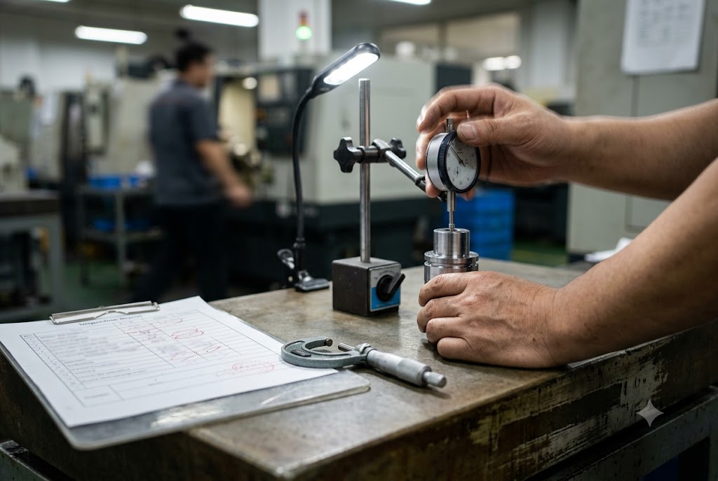
This mistake happens at the end of the process, after machining is complete. A Chinese micrometer or caliper calibrated in 0.001 mm increments is used to verify a dimension specified in inches. The inspector measures the part, reads a millimeter value, and must convert mentally to compare it against an inch tolerance.
Mental unit conversion at the point of measurement is a reliable source of inspection error 9. It is not a skills problem. It is a system design problem. The measurement tool and the specification should be in the same unit.
For critical dimensions on imperial-specified drawings, the cleanest solution is to require the supplier to report all measurements in millimeters against a metric-converted tolerance. Alternatively, send calibrated imperial gauges as part of a first-article inspection kit. Make the measurement system unambiguous at the point of inspection, not at the point of drawing interpretation.
| Mistake | Where It Happens | Consequence | Prevention |
|---|---|---|---|
| Mixed units in drawing | Drawing preparation | Scaled error on boundary features | Convert fully; one unit system only |
| STEP file in wrong unit | CAD export | Model/drawing scale mismatch | Confirm export unit; include unit in filename |
| Uncalibrated inspector gauges | Incoming/final inspection | Measurement conversion errors | Require metric reporting or supply imperial gauges |
| Surface roughness µm vs µin | Drawing interpretation | Finish 40× off specification | Always write unit abbreviation after Ra value |
| Thread callout not flagged | Tooling procurement | Wrong tap, wrong thread form | Confirm imperial tooling availability before production |
Conclusion
Unit confusion is predictable and preventable. Convert to millimeters before sending. Declare units clearly in the title block. Match your STEP file 10 to your drawing. Verify inspection instruments. These four habits alone will eliminate most unit-related scraps and delays on your China-sourced CNC orders.
Footnotes
1. Overview of China's metric system adoption and official measurement standards. ↩︎
2. Best practices for engineering drawing title blocks, including mandatory unit and projection fields. ↩︎
3. Guide to CNC machining surface roughness parameters Ra and Rz in µm and µin. ↩︎
4. How to read and write thread callouts, including UNC, UNF, and metric formats for CNC. ↩︎
5. Official ASME Y14.5 dimensioning and tolerancing standard for engineering drawings. ↩︎
6. English version of China's GB/T 4458 mechanical drawing dimensioning standard. ↩︎
7. Explanation of first-angle vs. third-angle orthographic projection with symbols and layouts. ↩︎
8. Guide to CAD file formats for CNC machining, covering STEP unit export and mismatch prevention. ↩︎
9. Surface roughness conversion chart covering Ra, RMS, and CLA across µm and µin units. ↩︎
10. CAD file preparation checklist for CNC quoting, including unit verification and STEP export rules. ↩︎



