 Skip to main content Skip to footer
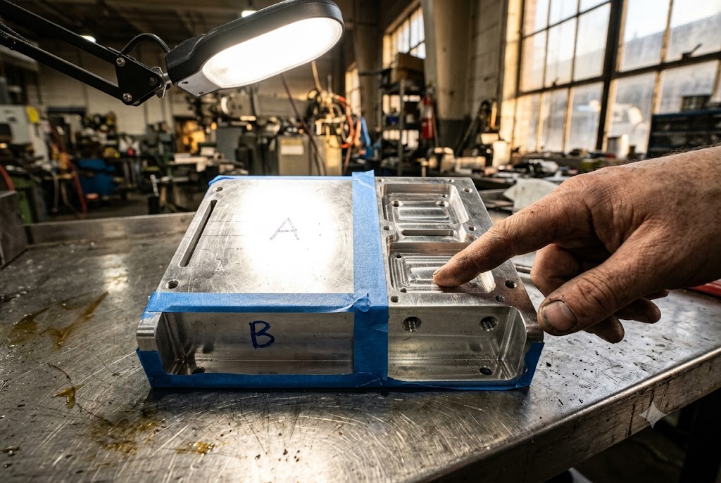
Every week, our team reviews shipments that failed cosmetic inspection — not because the factory made bad parts, but because nobody told them what "good" looked like.
Defining appearance requirements for CNC parts means dividing surfaces into A-side and B-side zones, expressing every cosmetic standard as a measurable criterion, specifying inspection conditions, using Pantone or RAL color references, retaining signed golden samples, and creating a separate cosmetic acceptance document that travels with every order.
Once you treat cosmetic requirements the same way you treat dimensional tolerances — specific, measurable, and documented — your rejection rate drops fast. Here is how to do it right.
What Cosmetic Standards Should I Include?
When we prepare cosmetic acceptance documents for our clients' parts, the biggest problem we see is vague language — and vague language costs money.
Cosmetic standards for CNC parts should include surface finish values in Ra, scratch and pit size limits by zone, edge break dimensions in millimeters, tool mark lay direction on visible faces, color references using Pantone or RAL codes, and inspection conditions such as lighting level, viewing distance, and viewing angle.
Why Vague Words Fail
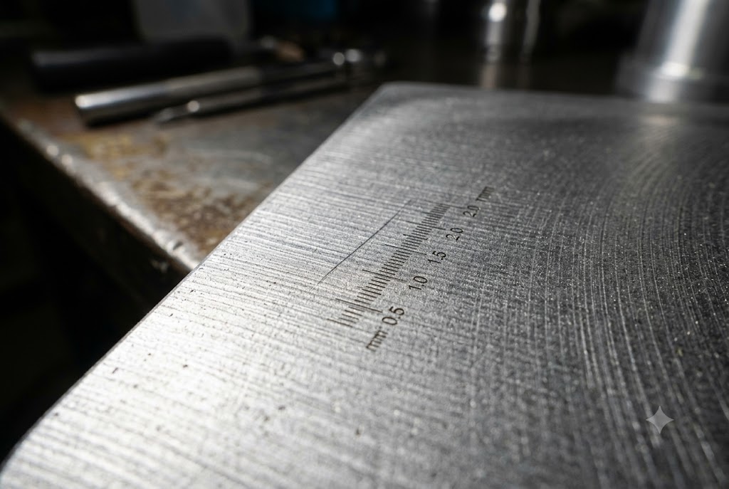
Words like "smooth," "clean," and "no defects" are not standards. They are opinions. A quality inspector in Shenzhen and a receiving inspector in Ohio will read those words and reach different conclusions on the same part. That difference becomes a dispute, a return shipment, and a lost production week for your customer.
Every cosmetic requirement must follow this pattern: criterion + unit + threshold. No exceptions.
Here are examples of unacceptable versus acceptable callouts:
| Unacceptable (Vague) | Acceptable (Measurable) |
|---|---|
| No scratches | No scratches longer than 2 mm on A-side surfaces |
| Smooth finish | Ra ≤ 0.8 µm on visible faces |
| No pits or dents | No pits larger than 0.3 mm² under 500 lux at 50 cm |
| Clean edges | Break all sharp edges 0.2–0.4 mm |
| Uniform color | Color to Pantone 433 C, Delta-E ≤ 2.0 |
Dividing the Part Into Zones First
Before you write a single cosmetic callout, divide the part into zones on the drawing. The two most important zones are:
A-side surfaces — Surfaces visible to the end user during normal use or on display. These carry your full cosmetic standard.
B-side surfaces — Surfaces hidden after assembly, inside enclosures, or facing mounting interfaces. These require only functional cleanliness and burr removal.
Applying the same cosmetic standard across the entire part forces the supplier to treat a hidden mounting face with the same care as the customer-facing front panel. That adds inspection time and cost with no visible benefit to your end user. Zone your drawing first, then assign requirements.
Surface Finish Callouts
Use ISO 1302 surface texture symbols 1 directly on the drawing. State Ra values for each zone separately. A typical breakdown might look like this:
| Zone | Ra Target | Notes |
|---|---|---|
| A-side faces | Ra ≤ 0.8 µm | Visible to end user |
| B-side faces | Ra ≤ 3.2 µm | Functional only |
| Internal bores | Ra ≤ 1.6 µm | Sealing or bearing surfaces |
| Threaded features | Per standard | No cosmetic callout needed |
Edge Break Requirements
Deburring is not optional, but "deburr all edges" is not an instruction — it is a suggestion. A machinist's interpretation ranges from one file pass across obvious burrs to a full chamfer on every feature. On a consumer-visible part, the difference between a 0.1 mm and 0.5 mm edge break changes the perceived quality in the hand of your end user.
State the callout as: Break all sharp edges 0.2–0.4 mm unless otherwise noted. Then specifically call out any features that need a different treatment.
Should I Define Scratch and Defect Limits?
Our sourcing team has seen entire containers of precision-machined panels rejected at the port because the acceptance document said "no visible scratches" — without defining what "visible" means or under what conditions.
Yes, you must define scratch and defect limits with explicit measurements. State the maximum allowable scratch length and width by surface zone, the maximum pit or dent area in mm², the maximum number of allowable defects per defined inspection area, and the exact inspection conditions under which those limits apply.

Inspection Conditions Are Part of the Standard
A scratch that is invisible under 300 lux at 70 cm becomes a clear reject under 1,000 lux at 30 cm. If you do not define the inspection conditions, the factory will default to their shop-floor conditions — which vary by shift, by season, and by how close the light is to the inspection table that day.
Every cosmetic acceptance document must specify:
| Inspection Parameter | Recommended Value |
|---|---|
| Viewing distance | 50 cm |
| Lighting level | 500–1,000 lux |
| Lighting color temperature | 3,000–5,300 K (neutral white) |
| Viewing angle | Approximately 45 degrees |
| Magnification | Not permitted for initial cosmetic inspection |
These five parameters transform "inspect the surface" from a judgment call into a repeatable procedure.
Defect Classification by Type
Not all defects carry the same risk. A scratch on a front panel is different from a scratch on the underside of a baseplate. Structure your defect limits around the zone and defect type:
Scratches — Define maximum length and width. Example: A-side surfaces, no scratches longer than 2 mm or wider than 0.1 mm.
Pits and dents — Define maximum area in mm². Example: No single pit larger than 0.3 mm² on A-side surfaces.
Tool marks — Specify whether tool marks are acceptable and, if so, in which direction. On brushed aluminum panels, controlled tool marks running in one direction are a feature. Random marks from multiple passes are a defect.
Contamination — Define acceptable versus unacceptable surface contamination. Machining coolant residue, fingerprints, and oxidation patches should each be addressed.
Allowable Defect Count
Even with measurable limits, you need to state how many defects are acceptable per inspection area. A single scratch on an A-side surface might be an acceptable manufacturing variation. Ten scratches of the same length on the same face indicate a process problem.
A practical approach: define the maximum number of acceptable defects per 100 cm² of A-side surface, and define a minimum spacing between adjacent defects so that a cluster of small marks does not pass simply because each individual mark is under the size limit.
When to Use a Cosmetic Acceptance Document
Engineering drawings are the right place for dimensional tolerances, material specifications, and surface finish callouts. They are not the right place for a full cosmetic acceptance standard, because cosmetic criteria evolve as production matures and field feedback refines what truly matters to end users.
A separate cosmetic acceptance document — referenced by revision number in the drawing title block — lets you update scratch limits, add approved defect examples, and revise inspection conditions without triggering a full engineering change order cycle 2. Keep this document controlled and send a current revision with every purchase order.
How Can I Ensure Consistent Visual Quality?
Consistent visual quality across a production run does not happen by accident. It requires a system — a reference point that every inspector on both sides of the supply chain can use to make the same decision.
Consistent visual quality for CNC parts requires retaining two to three signed golden samples from the first approved batch, sending one physically to the supplier as the binding cosmetic reference, specifying surface treatment parameters as drawing callouts rather than verbal instructions, and defining whether color consistency is required within a batch or across batches.
The Golden Sample System
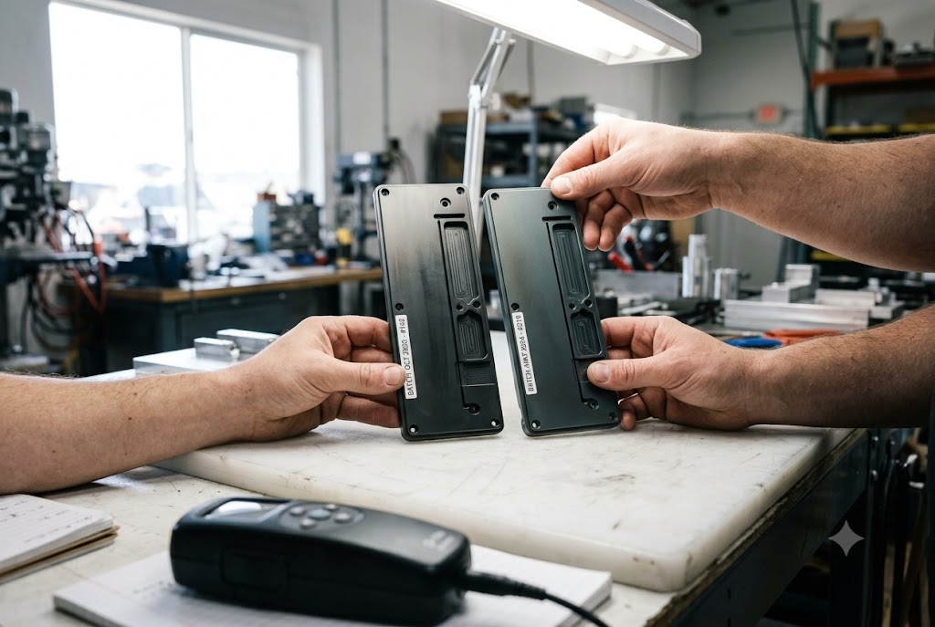
A drawing can specify Ra values and scratch limits. It cannot communicate the three-dimensional appearance of a bead-blasted surface 3, the depth of an anodize color, or the character of a brushed texture. A signed golden sample does.
Retain two to three samples from the first approved production batch. Sign and date each one. Send one to the supplier. Keep one at your receiving inspection station. Store one as a master reference.
The drawing note can state: Cosmetic appearance to match retained golden sample reference [part number, date]. This makes the sample legally binding as a specification.
Golden samples age. Anodize colors can shift with UV exposure. Establish a review schedule — typically every 12 months — and replace samples when they no longer accurately represent the standard.
Surface Treatment Parameters on the Drawing
Anodize appearance varies significantly with process parameters. A supplier choosing any single parameter differently from what you intended will produce a part that looks wrong even if it passed their own quality check. Put these callouts on the drawing:
- Anodize type: Type II (decorative) or Type III (hard anodize) 4
- Layer thickness range: e.g., 15–25 µm for Type II
- Sealing method: hot deionized water or nickel acetate
- Pre-anodize mechanical finish: e.g., bead blast to Ra 1.6 µm before anodize
Do not communicate these parameters verbally or by email. Verbal instructions change as personnel change. Drawing callouts stay with the part through every order, every revision, and every supplier change.
Color Specification
Color names are not color specifications. "Black," "dark gray," and "silver" are interpreted differently across anodizing baths, operators, and batches. Use a Pantone 5 or RAL color reference 6 with an allowable Delta-E tolerance 7.
For close-match applications, Delta-E ≤ 2.0 is a standard starting point. For applications where adjacent parts in different materials need to visually match, you may need Delta-E ≤ 1.0, which requires tighter process control and higher cost.
Within-Batch Versus Cross-Batch Consistency
Anodizing produces color through an electrochemical process sensitive to alloy lot, bath chemistry, current density, and temperature. Parts from two different production runs anodized to the same specification will often show a visible color shift when placed side by side.
Within-batch color consistency is achievable and should be a standard requirement. Cross-batch color consistency requires a physical color reference panel retained at the anodizer and a Delta-E limit measured against it for each new run. Decide which level you need before writing the requirement, then write the requirement to match.
Should I Use Reference Samples?
Our team places orders with multiple factories across China and Vietnam, and one lesson comes up every time a new part enters production: the factory's first interpretation of the drawing is never the same as the buyer's mental image of the finished part.
Yes, reference samples are essential for any CNC part with cosmetic requirements. Use signed golden samples as the binding appearance standard, physically send one to the supplier, retain one at your receiving inspection station, specify the sample as the legal reference on the drawing, and replace aging samples on a defined schedule.

What Reference Samples Actually Control
Reference samples are not just for color. They control every aspect of appearance that a drawing cannot fully describe:
Anodize color and depth — Under different lighting conditions, the same anodize layer can look noticeably lighter or darker. A physical sample under agreed inspection conditions eliminates that ambiguity.
Brushed texture uniformity — A drawing can call out lay direction, but it cannot communicate the visual density of a brush pattern, the spacing of lines, or the reflective character of the surface. A sample can.
Bead blast matte level — Ra values describe roughness but not the visual matte quality. Two surfaces with the same Ra value can look very different after anodizing depending on the bead blast media size and pressure.
Edge break character — The difference between a 0.2 mm and 0.4 mm edge break may both be within tolerance, but they feel different in the hand. For premium consumer products, a sample communicates which end of the tolerance band is preferred.
How to Create and Manage a Golden Sample Program
Follow these steps when setting up reference samples for a new part:
- Run a first article inspection 8 on the initial production batch. Approve dimensional and functional requirements first.
- Select two to three parts that best represent the desired cosmetic appearance. These become the golden sample candidates.
- Sign and date each candidate. Record the part number, drawing revision, and batch number on a label attached to each sample or on the sample itself.
- Send one signed sample to the supplier with written confirmation that this sample is the binding cosmetic reference for all future production.
- Retain one sample at your incoming inspection station as the acceptance reference.
- Store one sample as the master archive copy, in a stable environment away from UV exposure and humidity changes.
Sample Lifecycle and Replacement
Golden samples do not last forever. Anodize colors shift under UV exposure. Brushed aluminum develops oxidation. Bead-blasted surfaces accumulate handling marks.
Establish a review schedule. Inspect retained samples against the master archive every 12 months. If the color or surface has drifted beyond the Delta-E tolerance or the texture has changed visibly, run a replacement batch of golden samples and repeat the approval process.
Document the sample replacement. Keep a record of which sample was active for which production date range. This traceability matters when a customer disputes quality on a shipment from 18 months ago.
Supplier Management With Reference Samples
When we visit supplier factories as part of our audit process, one of the first things we check is whether the golden sample is present on the shop floor and whether the QC team knows what it is. A sample that sits in a manager's drawer does not improve production quality.
Require the supplier to keep the signed golden sample at the inspection station where cosmetic checks are performed. Include this as a requirement in your quality agreement. Verify it during factory audits and pre-shipment inspections 9.
The MIL-A-8625 anodizing specification 10 provides a widely adopted framework for defining anodize type and class on technical documents, and referencing it in your quality agreement ensures both parties are working from the same standard vocabulary.
Conclusion
Appearance requirements only work when they are specific, measurable, and shared. Zone your drawing, write measurable callouts, define inspection conditions, use color codes, and anchor everything to a signed golden sample. Do that, and your supplier can meet your standard every time.
Footnotes
1. How ISO 1302 symbols indicate surface texture requirements on technical drawings. ↩︎
2. How engineering change orders control formal revisions to manufacturing documents. ↩︎
3. Guide to bead blasting surface finish for CNC machined metal parts. ↩︎
4. Key differences between Type II and Type III aluminum anodizing under MIL-A-8625. ↩︎
5. Overview of the Pantone Matching System used for precise color specification. ↩︎
6. Overview of the RAL colour standard used in industrial coatings and manufacturing. ↩︎
7. How Delta-E values quantify acceptable color differences in manufacturing quality control. ↩︎
8. How first article inspection verifies that initial CNC parts meet all design specifications. ↩︎
9. Overview of CNC machining quality testing and inspection stages. ↩︎
10. MIL-A-8625 military specification for anodic coatings on aluminum parts. ↩︎



