 Skip to main content Skip to footer
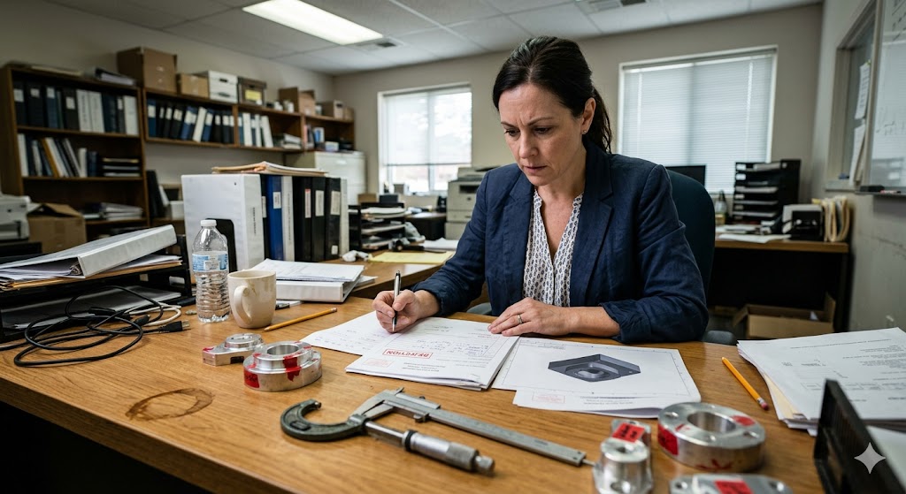
We have seen it happen more times than we can count. A buyer sends a 3D CAD file, writes "high quality" in the chat, and then wonders why the first shipment fails incoming inspection. Vague instructions cost real money.
Setting quality standards for imported custom CNC machining parts from China requires a fully toleranced 2D drawing, a written Quality Agreement covering AQL levels and inspection methods, explicit CTQ feature identification, and material certification by alloy and temper — all agreed in writing before production begins.
Get these documents right before you place an order, and you give yourself a clear, enforceable baseline. Skip them, and every quality dispute becomes a negotiation.
What Quality Requirements Should You Define Before Production Begins?
Our team reviews supplier quotations every week, and the single most common gap we see is a buyer who cannot clearly state what "acceptable" looks like. Suppliers fill that gap with their own judgment — and their judgment is optimized for speed, not your spec.
Before production begins, you must define CTQ features, surface finish values, material alloy and temper, defect classification tiers with AQL levels, and the inspection method for each critical dimension — all in a signed Quality Agreement that supplements the drawing and purchase order.
Start With Your Drawing
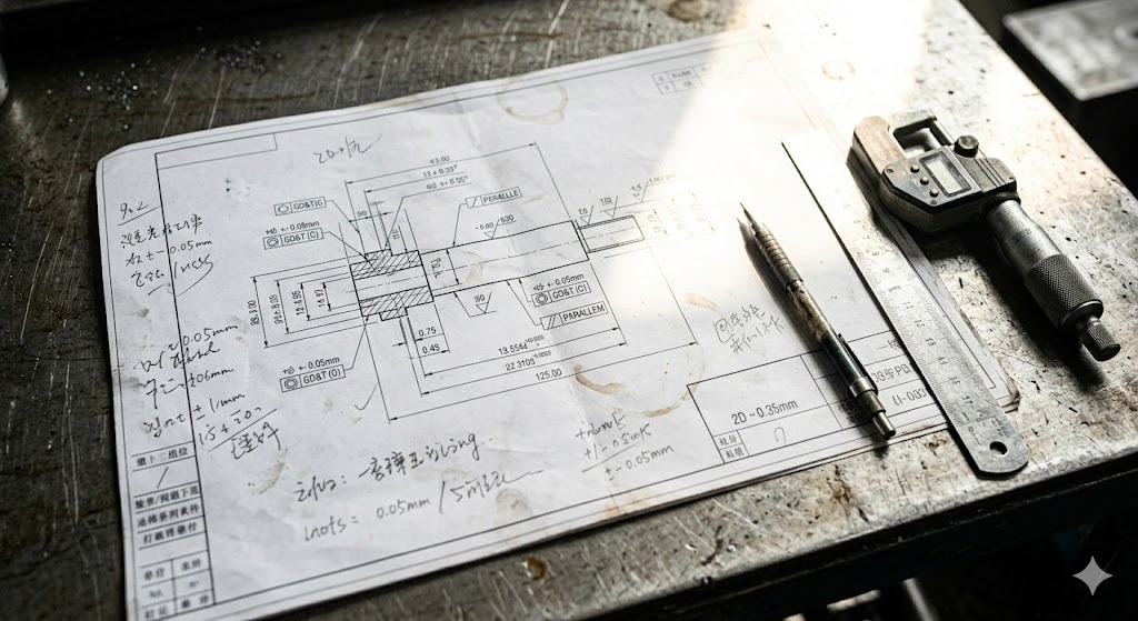
A drawing is the only document that creates an objective acceptance baseline. A 3D CAD file alone is not enough. It shows geometry but does not communicate tolerance intent.
Your 2D drawing must include:
- Every critical dimension with explicit tolerance callouts
- A datum reference scheme for GD&T features 1
- Surface finish symbols with numerical Ra or Rz values
- Material specification by alloy designation and temper
- A title block with revision number and date
Define CTQ Features Explicitly
CTQ 2 stands for Critical-to-Quality. These are the specific features where an out-of-spec condition causes functional failure, assembly interference, or safety risk.
Mark CTQ features on the drawing. Use a bubble callout or a dedicated CTQ table in the drawing notes. This tells the supplier which dimensions need the most care and which will trigger a lot rejection if they fall outside tolerance.
Non-CTQ features should carry looser tolerances that match the supplier's natural process capability. Over-tolerancing non-critical features drives up cost and creates unnecessary rejection disputes without improving part performance.
Use ISO 2768 for Untoleranced Dimensions
Every drawing has features that are not explicitly toleranced. Do not leave these undefined. Reference ISO 2768 3 as the default standard.
| ISO 2768 Grade | Common Name | Typical Application |
|---|---|---|
| f | Fine | Precision machined parts with close fits |
| m | Medium | General CNC machining, most common in China shops |
| c | Coarse | Non-critical features, structural parts |
| v | Very Coarse | Raw castings, non-functional surfaces |
ISO 2768-m is the most widely understood baseline in Chinese CNC shops. Specifying it eliminates ambiguity about what tolerance applies to features without explicit callouts.
Classify Defects Into Three Tiers
Before production begins, agree on a defect classification system with your supplier. Without it, every incoming quality dispute becomes an argument about what counts as a real defect.
| Defect Class | Definition | AQL Level |
|---|---|---|
| Critical | Safety risk or part completely non-functional | 0 (zero tolerance) |
| Major | Impairs function or assembly fit | 1.0 or tighter |
| Minor | Cosmetic or non-functional deviation | 2.5 or as agreed |
Communicate this classification explicitly in your Quality Agreement. It gives your incoming QC team and any third-party inspector a precise, defensible protocol for batch disposition.
Specify Surface Finish Numerically
Chinese suppliers interpret visual surface quality subjectively. They will ship the cheapest finish that passes a visual check unless you specify a numerical roughness standard.
Use Ra or Rz values 4. Examples:
- Ra 0.8 µm — precision ground or lapped surfaces
- Ra 1.6 µm — fine turning or milling, close-tolerance bores
- Ra 3.2 µm — standard machined surfaces, general use
- Ra 6.3 µm — rough machined, non-critical areas
State that the value will be verified with a profilometer and that measurement is a contractual requirement in the Quality Agreement.
How Can You Align Your Drawings, Inspection Plan, and Acceptance Criteria?
In our experience managing production orders across dozens of Chinese factories, the biggest source of incoming inspection failures is not a bad supplier — it is a misaligned document set. The drawing says one thing, the purchase order says another, and the supplier uses neither.
Aligning drawings, inspection plans, and acceptance criteria means issuing a single, consistent document package — current drawing revision, written inspection plan specifying measurement methods per CTQ feature, and a signed Quality Agreement — so that every party works from the same written standard.

Issue a Complete Document Package
Every production order should include three core documents:
- Current drawing revision — with revision number, date, and all tolerance and surface finish callouts
- Inspection plan — listing each CTQ feature, the measurement method, the instrument required, and the acceptance limit
- Quality Agreement — signed by both parties, covering AQL levels, material certification, defect classification, corrective action protocol, and packaging requirements
These documents must be consistent with each other. If the drawing specifies a bore diameter of 25.000 ± 0.010 mm, the inspection plan must list that dimension, name the measurement instrument (calibrated bore gauge or CMM), and state the acceptance limit as 24.990–25.010 mm.
Match Measurement Method to Feature Complexity
A quality standard that specifies a dimension but not the measurement method leaves the supplier free to use a less accurate instrument. That instrument will pass parts that your CMM would reject.
| CTQ Feature Type | Recommended Measurement Method |
|---|---|
| Complex GD&T, tight tolerances | CMM (Coordinate Measuring Machine) |
| Bores and shafts | Calibrated micrometers, bore gauges |
| Surface roughness | Profilometer (contact type) |
| Threads and fits | Calibrated go/no-go gauges |
| Material composition | XRF analyzer or mill certificate with chemical data |
Write the required instrument into the inspection plan. If the supplier does not own the instrument, they must subcontract the measurement to an accredited lab.
Define AQL Sampling Under ISO 2859
AQL (Acceptable Quality Limit) 5 is a statistical sampling standard. It defines how many defects are permissible in a sample drawn from a batch before the entire lot is rejected.
Specify AQL under ISO 2859 6 in your purchase agreement. This gives your incoming QC team a precise, defensible acceptance and rejection protocol.
A common approach for mechanical parts:
- AQL 0 for critical defects (any critical defect in the sample rejects the lot)
- AQL 1.0 for major defects
- AQL 2.5 for minor defects
Without a pre-agreed AQL level, the supplier can argue that a batch with 5% defective parts still meets an undefined quality expectation. With AQL in writing, there is no argument.
Require a First Article Inspection Report
Before the first full production run, require a First Article Inspection (FAI) 7. The supplier measures every CTQ feature on a sample of five to ten parts and submits a report with actual measured values against drawing tolerances.
An FAI does three things. It confirms the supplier's process is capable. It confirms both parties are measuring the same features in the same way. And it creates a documented baseline that pre-production samples were approved before mass production began.
Use Formal Change Control for Every Revision
Any revision to a drawing, tolerance, material specification, or inspection method must follow a formal change process. Issue a new drawing revision number. Get written acknowledgment from the supplier. Re-run an FAI or sample approval before production resumes.
Suppliers who accept undocumented verbal changes, or who make process adjustments without a corresponding drawing revision, are operating outside the quality system. The resulting production output has no traceable standard against which it can be accepted or rejected.
Should You Define Cosmetic and Dimensional Standards Separately?
Our production coordinators handle supplier disputes regularly. The most time-consuming disputes are never about a dimension that was clearly out of tolerance. They are about a scratch, a burr, a surface mark — something that one party calls a defect and the other calls normal machined finish. Cosmetic standards need their own rules.
Yes, you should define cosmetic and dimensional standards separately. Dimensional standards use numeric tolerances and measurable acceptance criteria. Cosmetic standards require a visual reference — a written defect zone map, a physical limit sample, or both — agreed and signed before production begins.

Why They Require Different Tools
Dimensional standards are objective. A bore is either within tolerance or it is not. A CMM (Coordinate Measuring Machine) 8 measurement gives a number. The number either falls inside the acceptance range or it does not.
Cosmetic standards are subjective by nature. A surface mark that your customer considers a reject may look acceptable to a Chinese factory QC inspector who has never seen your end application. Without a written and mutually agreed cosmetic standard, every cosmetic dispute becomes a negotiation.
Define Defect Zones on the Part
Not all surfaces on a part are equally visible or functional. A cosmetic defect on a hidden mounting flange is not the same as the same defect on a customer-facing surface.
Divide the part into zones:
| Zone | Description | Cosmetic Acceptance Level |
|---|---|---|
| Zone A | Customer-visible, high-visibility surfaces | Strictest — no scratches, marks, or tool lines visible at 500 mm normal viewing distance |
| Zone B | Assembly-visible but not customer-facing | Moderate — minor marks acceptable if within defined size limits |
| Zone C | Hidden after assembly, structural surfaces | Relaxed — functional integrity is the only requirement |
Mark these zones on a drawing or photograph. Include the zone map in the Quality Agreement.
Specify Cosmetic Defect Limits in Writing
For each zone, write specific limits. Use objective language wherever possible.
Examples:
- Zone A: No scratches longer than 3 mm or deeper than Ra 1.6 µm. No pits larger than 0.5 mm diameter. No burrs detectable by glove-hand contact.
- Zone B: Scratches up to 10 mm acceptable if not visible at 300 mm. Pits up to 1.0 mm acceptable in non-sealing areas.
- Zone C: Cosmetic appearance not inspected. Burrs must not interfere with assembly or function.
Use a Physical Limit Sample
Written descriptions of cosmetic standards are useful. Physical limit samples are better. A limit sample is a production part, or a surface panel, that represents the worst acceptable condition.
Produce a limit sample during the FAI stage. Have the supplier sign and retain a copy. Have your quality team sign and retain a copy. During production inspections, the inspector compares production parts against the limit sample, not against a subjective judgment.
Apply the Same Defect Classification Logic
Apply your three-tier defect classification — critical, major, minor — to cosmetic defects as well as dimensional ones. A scratch that prevents proper sealing is a major defect. A shallow tool mark in a Zone C area is a minor defect. A cosmetic flaw that creates a sharp edge risk is a critical defect.
This prevents the situation where a supplier argues that a cosmetic failure is "just appearance" and should not trigger a lot rejection.
What Documents Should Suppliers Follow to Meet Your Quality Expectations?
When we place orders with factories on behalf of our clients, we always issue a defined document set before a single part is cut. A supplier working without the right documents is working without a target. What they produce is their interpretation of your requirements — not yours.
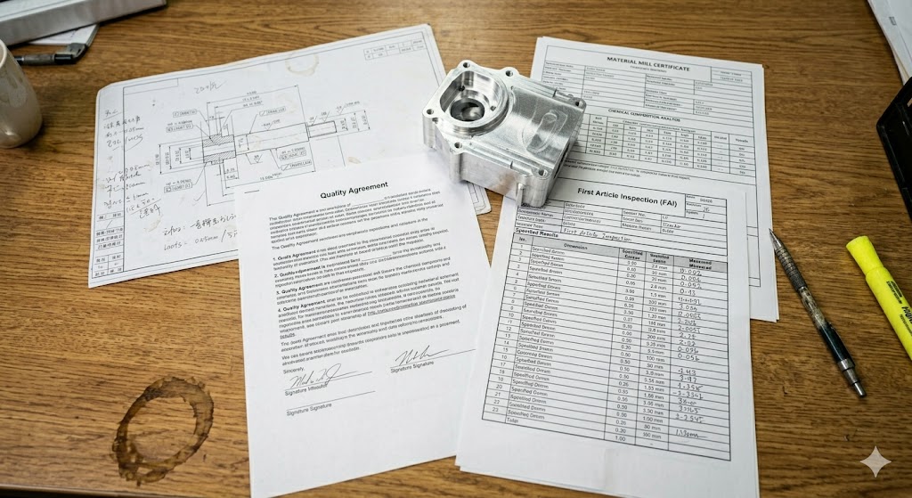
Suppliers should follow four core documents: a fully toleranced 2D drawing with revision control, a written Quality Agreement covering AQL, inspection methods, and defect classification, a material specification requiring mill certificates traceable to the production batch, and a First Article Inspection report accepted before mass production.
The Four Core Documents
Each document plays a specific role. Together they create a complete, enforceable quality system for a custom CNC machining order.
Document 1: The Drawing
The drawing is the primary technical standard. It must include:
- All critical dimensions with explicit tolerance callouts
- GD&T symbols and datum scheme where applicable
- Surface finish requirements with Ra or Rz values
- Material specification by alloy and temper
- Title block with current revision number and date
The drawing must be issued at a specific revision. Every change creates a new revision. Suppliers must acknowledge the current revision in writing before production.
Document 2: The Quality Agreement
The Quality Agreement consolidates all quality requirements into one signed reference. It covers:
- Drawing revision in effect
- Tolerance standard for untoleranced dimensions (e.g., ISO 2768-m)
- CTQ feature list
- Defect classification and AQL levels
- Inspection methods and required instruments
- Material certification requirements
- Surface finish standard and measurement method
- Cosmetic standard, zone map, and limit sample reference
- Packaging and labeling requirements
- Corrective action protocol for nonconformances
Both parties must sign the Quality Agreement before production begins. Its existence and mutual signature is what enables you to reject nonconforming goods and demand correction without a dispute about what was originally agreed.
Document 3: Material Certification
Specify material by alloy designation and temper, not by category. "Aluminum" is not a material specification. "Al 6061-T6" is.
Require a mill certificate 9 traceable to the specific batch used for production. The certificate must include chemical composition data. Without it, you cannot verify that the supplier did not substitute a lower-cost alloy within the same material family.
Common alloy and temper specifications for CNC machining:
| Material Category | Specific Designation | Key Properties |
|---|---|---|
| Aluminum | Al 6061-T6 10 | Good machinability, structural grade |
| Aluminum | Al 7075-T6 | High strength, aerospace grade |
| Stainless Steel | SS 316L | Corrosion resistant, low carbon |
| Stainless Steel | SS 304 | General purpose, food grade |
| Titanium | Ti-6Al-4V (Grade 5) | High strength-to-weight, aerospace |
| Carbon Steel | 1045 | General structural, heat treatable |
Document 4: First Article Inspection Report
Before mass production, require a FAI. The supplier measures every CTQ feature on a sample of five to ten parts and submits actual measured values against drawing tolerances. You review, approve, and sign the FAI report. Only after approval does mass production proceed.
The FAI also confirms that both parties are using the same measurement methods and instruments. If the supplier's CMM reads a different value than your incoming inspection instrument, you find and resolve that discrepancy at five parts — not at five thousand.
Treat Documents as a Living System
Quality standards are not set once and forgotten. They require formal change control. Any revision to a drawing, tolerance, or material specification must be:
- Issued as a new drawing revision
- Acknowledged in writing by the supplier
- Re-validated through a sample or FAI before production resumes
Verbal changes are not changes. An email from a sales representative is not a drawing revision. Only a formally issued, revision-numbered document creates an enforceable standard.
Conclusion
Set your quality standards in writing, before production begins. A complete drawing, a signed Quality Agreement, material certification, and a First Article Inspection report give you a system that is enforceable, traceable, and dispute-resistant from day one.
Footnotes
1. Formlabs guide to GD&T: how geometric dimensioning and tolerancing communicates design intent to manufacturers. ↩︎
2. SafetyCulture explains Critical-to-Quality (CTQ): translating customer requirements into measurable engineering specifications. ↩︎
3. ISO 2768-1: the international standard for general tolerances on linear and angular dimensions without individual callouts. ↩︎
4. Wevolver in-depth comparison of Ra and Rz surface roughness parameters and when to apply each in precision manufacturing. ↩︎
5. QIMA's practical guide to AQL: how Acceptable Quality Limit sampling works in product inspection decisions. ↩︎
6. ANSI Blog overview of ISO 2859-1:2026: the updated AQL sampling standard for lot-by-lot inspection by attributes. ↩︎
7. Fictiv comprehensive guide to First Article Inspection: purpose, process, and approval workflow before mass production. ↩︎
8. Creaform3D primer on coordinate measuring machines (CMMs): types, working principles, and quality control applications. ↩︎
9. The Fabricator FAQ on mill test reports: how MTRs certify metal alloy composition, traceability, and batch compliance. ↩︎
10. Detailed technical profile of Al 6061-T6 aluminum: composition, temper designation, machinability, and common CNC applications. ↩︎



