 Skip to main content Skip to footer
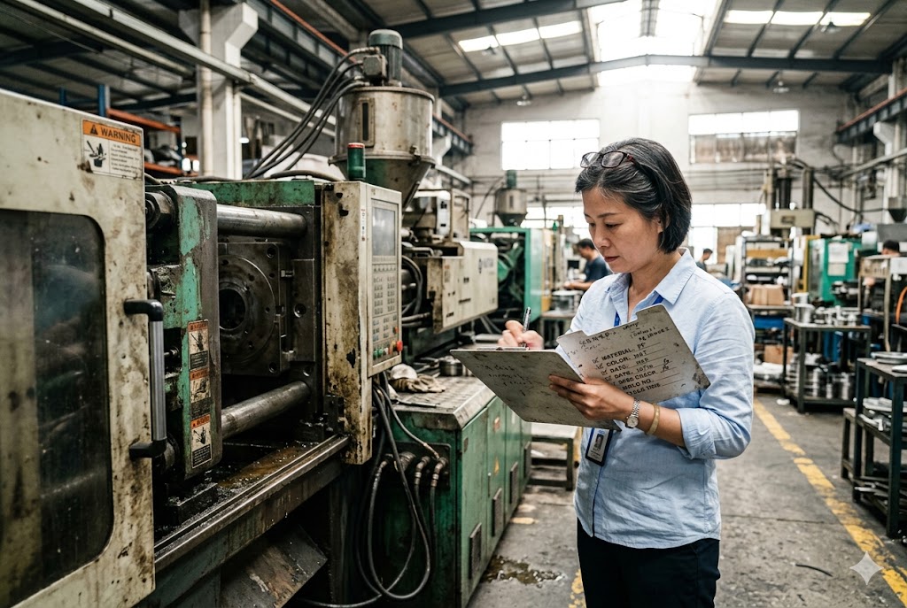
Every time our team reviews a new project request involving thin-wall or large structural injection molding, we see the same pattern: buyers have been burned before. A supplier quoted the job, made first-article samples, and then struggled to hold tolerances in production. We've spent years visiting factories across China and Vietnam to understand exactly why this happens — and more importantly, how to tell which suppliers can actually deliver.
Thin-wall injection molding and large structural molding both require specialized machines, high-strength mold steel, mold flow simulation, and disciplined process control. Chinese suppliers capable of these jobs will provide injection pressure ratings, Moldflow simulation reports, and SPC production data — not just machine tonnage and a sample price. Suppliers who cannot provide this data are not ready for these parts.
The gap between a capable supplier and an incapable one is not always obvious from a factory tour or a price sheet. The rest of this article gives you the exact questions to ask and the red flags to watch for.
What Are the Common Defects in Thin-Wall Injection-Molded Parts from China and How Can I Prevent Them?
When we audit suppliers for thin-wall molding projects, the defect list comes up fast. Short shots, burn marks, warpage, and sink marks are the most common complaints we hear from buyers who have already had a bad experience.
The most common defects in thin-wall injection-molded parts from China are short shots, burn marks, warpage, and sink marks. Short shots and burn marks usually come from poor venting or inadequate injection speed. Warpage and sink marks come from uneven cooling or incorrect resin selection. All four can be prevented with correct machine specs, venting design, and mold flow simulation before tooling is cut.
Why Short Shots Happen
A short shot means the cavity did not fill completely. In thin-wall molding, the melt starts to freeze as soon as it touches the cold mold wall. If injection speed is too slow, the part freezes before fill is complete.
The machine matters more than most buyers realize. Tonnage alone tells you nothing. You need to ask for the injection rate in cubic centimeters per second and the maximum injection pressure in bar. For true thin-wall work — wall thickness below 1.0 mm with a flow-length-to-thickness (L/T) ratio above 100:1 — you need machines capable of injection pressures up to 2,000 bar and injection rates far above standard presses. A supplier running a standard machine with an undersized injection unit will produce short shots regardless of how much they tune the process.
The Role of Resin Selection
Resin grade is the second variable most suppliers get wrong. Every resin has a melt flow index (MFI) 1. A standard-flow grade of polypropylene might fill a 2.0 mm wall cavity with no problem. The same grade will short-shot at 0.6 mm. For thin-wall applications, you need a high-flow grade of the same base polymer — specifically formulated for thin-wall work.
When reviewing a supplier's process proposal, ask for the MFI of the exact resin grade they plan to run. If they give you a resin family name without a grade specification, push back.
Burn Marks and Venting
Burn marks appear where trapped air cannot escape fast enough during high-speed injection. In thin-wall cavities, injection happens in fractions of a second. Air has almost no time to evacuate through conventional venting.
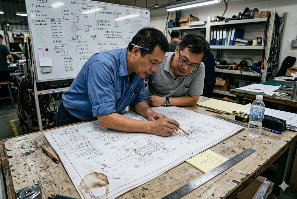
Ask to see the mold drawings. Look for documented vent locations and vent depth specifications. Vent depth for thin-wall cavities is typically in the 0.01–0.02 mm range — shallow enough to prevent flash but deep enough to evacuate air. If a supplier cannot show you the venting design in their drawings, treat that as a quality risk.
| Defect | Root Cause | Prevention |
|---|---|---|
| Short shot | Low injection speed or pressure, high-viscosity resin | High-speed machine, high-MFI resin grade |
| Burn mark | Trapped air, insufficient venting | Documented vent locations and depths in mold drawing |
| Warpage | Uneven cooling, differential internal stress | Mold flow simulation, conformal cooling inserts |
| Sink mark | Thick cross-sections, insufficient packing pressure | DFM review, gas-assisted injection molding (GAIM) |
Warpage and Cooling Design
Warpage in thin-wall parts comes from uneven cooling. One side of the part cools faster than the other. Internal stress builds up. The part bends when it ejects.
The fix starts before the mold is cut. Mold flow simulation 2 — software like Moldflow — models how heat distributes through the cavity during cooling. It predicts where warpage will occur and allows engineers to adjust cooling channel layout, gate location, and wall thickness before any steel is machined. Require the supplier to deliver the warpage deflection output from their simulation as part of DFM approval. If they treat simulation as optional, that is a red flag.
How Do I Verify That a Chinese Supplier Has the Right Equipment for Large-Part Injection Molding?
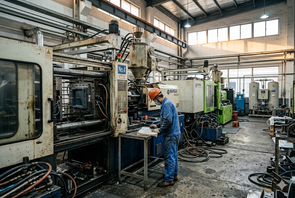
Our team has walked the factory floor of suppliers claiming large-part capability, only to find machines with no gas-assist hookup, no nitrogen generation equipment, and cooling circuits drilled straight through the mold with no regard for part geometry. Equipment verification is not a one-question conversation.
To verify a Chinese supplier's large-part injection molding capability, confirm their machine platen size, maximum shot weight, gas-assist nitrogen generation setup, and mold temperature control system. For parts exceeding 500 mm in any dimension, also require mold flow simulation results showing warpage predictions. A supplier who cannot provide all of these is not equipped for large structural molding.
Machine Platen Size and Shot Weight
The first check is simple. The part has to fit on the machine's platen. Ask for the tie-bar spacing and platen dimensions — not just the tonnage. A large automotive panel or appliance housing may require a platen of 2,000 mm × 1,600 mm or larger.
Shot weight matters too. The machine's injection unit must be able to deliver enough melt volume to fill the cavity in one shot without hesitation. Ask for the maximum shot weight in grams for the machine they intend to use on your part.
Gas-Assisted Injection Molding (GAIM)
Large structural parts often have thick ribs, bosses, or handles. These thick cross-sections create sink marks on the visible surface. Gas-assisted injection molding (GAIM) 3 is the standard engineering solution.
In GAIM, the mold fills partially with plastic melt. Then pressurized nitrogen gas is injected into the melt through a gas pin. The gas hollows out the thick cross-sections, eliminating sink marks, reducing part weight, and lowering the injection pressure required — which means a smaller machine can run a larger part.
The key question when auditing a GAIM-capable supplier: Do they own their own nitrogen generation equipment, or do they rely on bottled gas? In-house nitrogen generation provides more stable gas pressure during the injection cycle. Bottled gas introduces variability in pressure delivery and supply chain risk. A supplier with in-house nitrogen generation demonstrates a higher level of process seriousness.
Mold Temperature Control
Large parts cool slowly. Inconsistent mold temperature leads to warpage variation between production runs — even if the first-article sample passed inspection. Ask how the supplier controls mold temperature: water-cooled circuits, oil-temperature controllers, or both. Ask whether they monitor mold surface temperature during production and how they respond when it drifts.
| Equipment Check | What to Ask | Red Flag |
|---|---|---|
| Machine platen | Tie-bar spacing and platen dimensions (mm) | Supplier only quotes tonnage |
| Injection unit | Maximum shot weight (g) and injection rate (cc/s) | No specification available |
| Gas assist (GAIM) | In-house nitrogen generation vs. bottled gas | Only bottled gas, no in-house generation |
| Mold temperature | Temperature controller type, monitoring method | No documentation, "we just use water" |
| Cooling design | Straight-drilled vs. conformal cooling circuits | No cooling layout in mold drawings |
Conformal Cooling — A Proxy for Technical Maturity
Conformal cooling channels 4 follow the shape of the mold cavity instead of running in straight lines. They deliver 18–26% faster cooling times and meaningfully reduce warpage in complex large-part geometry compared to conventional straight-drilled cooling.
Conformal cooling requires additive manufacturing — metal 3D printing — to produce the cooling inserts. Not every supplier has this capability. But asking the question tells you a lot. A supplier who knows what conformal cooling is, can describe their experience with it, and can show you a part produced with it is operating at a different technical level from a commodity shop.
What Mold Flow Analysis Tools Should a Chinese Factory Use for Complex Thin-Wall or Large Structural Parts?
When our engineers review DFM packages from Chinese suppliers, we can tell very quickly whether a factory uses simulation as a real engineering step or just checks a box to close a sale. The difference shows up in the deliverables they can provide.
Chinese factories producing complex thin-wall or large structural injection-molded parts should use Autodesk Moldflow 5 or equivalent simulation software — such as Moldex3D 6 — to analyze fill pattern, cooling uniformity, warpage deflection, and weld line location before mold design is finalized. The supplier should provide the warpage deflection output and fill pattern report as formal deliverables at DFM approval, not as optional extras.

What Mold Flow Simulation Actually Covers
Mold flow simulation is not a single analysis. It includes multiple modules that address different risk areas. A competent supplier will run at least these four:
Fill analysis shows how the melt front advances through the cavity. It identifies locations prone to short shots, weld lines, and air traps before any steel is cut.
Cooling analysis models how heat is removed from the part during the cooling phase. It identifies hot spots where cooling channels are too far from the cavity surface. Hot spots cause sink marks and warpage.
Warpage analysis predicts the deflection of the finished part after ejection. For large structural parts, this output should show quantified warpage values in millimeters across the part surface — not just a color gradient.
Fiber orientation analysis applies to glass-filled or fiber-reinforced resins. Fiber orientation affects both mechanical strength and warpage. If your part is made from GF-PA6, GF-PP, or similar filled grades, fiber orientation analysis is not optional.
Evaluating the Simulation Deliverable
Anyone can run a simulation. Not everyone can interpret the results and act on them. Ask the supplier what design changes were made to the mold or part based on their simulation results. If the answer is "we just confirmed the design was okay," the simulation was probably run for show.
A supplier who uses simulation as a real engineering tool will describe gate location adjustments, changes to cooling channel routing, or wall thickness modifications that came out of the analysis.
| Simulation Module | Purpose | Required For |
|---|---|---|
| Fill analysis | Predicts short shots, weld lines, air traps | All thin-wall and large structural parts |
| Cooling analysis | Identifies hot spots and cooling imbalance | Large structural parts, complex geometry |
| Warpage analysis | Quantifies part deflection after ejection | All parts with tight flatness or profile tolerances |
| Fiber orientation | Models fiber alignment in filled resins | GF-PA, GF-PP, LFT, and other fiber-filled grades |
Mold Steel Grade as a Simulation Companion
Mold flow simulation tells you what the tool design should look like. Mold steel selection tells you whether the tool will survive the pressures required to execute that design in production.
Thin-wall molds operate under extreme cyclic pressure loads. The cavity inserts must be made from high-strength tool steel 7 — P20, 1.2738, or hardened H13. Suppliers quoting thin-wall tooling with standard S50C or mild steel mold bases and no hardened inserts are under-specifying the tool. The mold will fatigue, deform, or crack at the parting line under production conditions, usually after a few thousand shots — right when you are ramping up production volume.
How Do Lead Time and Cost Change for Thin-Wall Injection-Molded Parts Compared to Standard Parts in China?
We get this question from purchasing managers every time a project moves from concept to sourcing. The honest answer is that both lead time and cost increase — but the reasons are often misunderstood, and the cost increase is predictable if you know what to look for.
Thin-wall injection-molded parts from China typically cost 20–40% more in tooling than standard-wall equivalents and require 4–6 weeks longer for mold build due to hardened steel cavity requirements and precision EDM machining. Piece-part pricing is often competitive or lower than standard molding because cycle times are shorter — under 5 seconds for packaging parts — but only when the supplier has the right high-speed equipment.

Tooling Cost and Lead Time
The mold cost increase for thin-wall tooling comes from three places. First, hardened cavity steel 8 costs more and requires more machining time than standard pre-hardened P20. Second, thin-wall cavities require tight dimensional tolerances on the core and cavity surfaces — often ±0.01 mm or better — which requires precision EDM and grinding rather than standard CNC milling. Third, venting design is more complex and must be machined with greater precision.
A standard injection mold for a simple consumer part might be built in 4–5 weeks. A thin-wall mold for the same part geometry, built to the correct steel and tolerance specification, typically takes 8–10 weeks. Suppliers who quote thin-wall tooling on a standard lead time are either cutting corners on specification or underestimating the job.
Piece-Part Pricing Dynamics
Thin-wall molding has a counter-intuitive cost advantage at the piece-part level: cycle times are very short. A thin-wall food container might cycle in 3–4 seconds. A standard-wall part of similar size might cycle in 12–18 seconds. Faster cycles mean more parts per hour from the same machine, which lowers the per-piece machine cost.
However, this advantage only materializes when the supplier has the right equipment. A slow machine running a thin-wall tool at reduced injection speed to prevent flash will run extended cycles, eliminating the cycle time benefit and introducing defect risk at the same time.
The SPC Requirement
The most underappreciated cost factor is process validation. A first-article sample from a capable supplier does not guarantee production consistency. Thin-wall parts are sensitive to fractions-of-a-second variation in injection timing. Any delay in injection changes the freeze-off profile and produces dimensional variation shot-to-shot.
Require the supplier to provide Statistical Process Control (SPC) 9 data on cycle time and key dimensions across a minimum 500-shot production window from an equivalent prior job. This is the only evidence that their process is stable under real production conditions — not just optimized for first-article approval.
| Cost / Lead Time Factor | Standard Wall Molding | Thin-Wall Molding |
|---|---|---|
| Mold steel grade | P20 pre-hardened | H13 hardened inserts, 1.2738 |
| Mold build lead time | 4–5 weeks | 8–10 weeks |
| Tooling cost premium | Baseline | +20–40% |
| Piece-part cycle time | 12–18 seconds (typical) | 3–5 seconds (packaging) |
| Machine requirement | Standard injection unit | High-pressure, high-speed unit |
| Validation requirement | First-article inspection | 500-shot SPC production window |
In-Mold Labeling as a Cost Factor
If your thin-wall part requires decoration, ask whether the supplier has in-mold labeling (IML) 10 capability. IML integrates the label directly into the molding cycle — a pre-printed label is placed in the mold cavity before each shot. The label bonds to the part surface during injection. This eliminates post-mold decoration, reduces handling, and allows cycle times as fast as 3–4 seconds per shot on high-cavitation molds.
An IML-capable supplier is not just demonstrating thin-wall competence. They are demonstrating the automated part handling and cycle time discipline required for high-volume consumer packaging. That combination of capabilities represents a different tier of supplier from one who runs thin-wall parts on manual operations.
Conclusion
Choosing the right Chinese supplier for thin-wall or large structural injection molding comes down to documented evidence — machine specs, simulation outputs, mold steel grades, and SPC production data. Ask for all of it. Suppliers who can deliver it are ready for your project.
Footnotes
1. Explains melt flow index and its critical role in selecting resins for thin-wall injection molding. ↩︎
2. Autodesk Moldflow simulates fill, cooling, warpage, and deflection before tooling is cut. ↩︎
3. Comprehensive guide to gas-assisted injection molding process, benefits, and applications. ↩︎
4. Overview of conformal cooling channels and how additive manufacturing enables their production. ↩︎
5. Autodesk Moldflow feature set for injection mold design, plastic part analysis, and process optimization. ↩︎
6. Moldex3D true-3D simulation software for predicting defects and optimizing injection mold design. ↩︎
7. H13 tool steel properties, heat treatment, and why it is the preferred choice for high-volume molds. ↩︎
8. Injection mold steel selection guide comparing P20, H13, and S136 grades for different applications. ↩︎
9. How Statistical Process Control improves injection molding quality and process stability. ↩︎
10. Differences between in-mold labeling and in-mold decorating and their use in thin-wall packaging. ↩︎



