 Skip to main content Skip to footer

Every time we set up a Swiss-type lathe 1 run for a new client part, the same two numbers decide everything: spindle speed and feed rate. Get them wrong and the surface looks torn, the cycle time bloats, and tools die early.
Spindle speed and feed rate on Swiss-type lathes directly control surface finish and machining efficiency. Spindle speed must target the correct Surface Feet per Minute for the material, while feed rate per revolution mathematically drives surface roughness. Together, they determine Ra values, tool life, and total cycle time.
Both variables interact with each other and with your material. Understanding that relationship is what separates a clean, repeatable part from a scrap pile.
What RPM Range Do Top-Tier Swiss-Type Lathes in China Factories Typically Operate At?
Our production lines run a mix of Swiss-type platforms, and the RPM question comes up with almost every new client inquiry. Raw RPM numbers alone tell you very little without context.
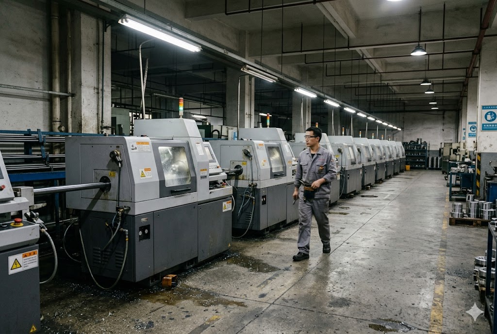
Top-tier Swiss-type lathes in Chinese factories typically operate main spindles at 8,000 to 15,000 RPM, with dedicated micro-machining models reaching 20,000 RPM or higher. The correct operating RPM depends entirely on part diameter and material, not on the machine's maximum rating.
RPM vs. Surface Speed: The Number That Actually Matters
RPM is a machine setting. Surface Feet per Minute (SFM) 2 — or Surface Meters per Minute (SMM) — is the cutting variable that actually governs tool performance and finish quality. As bar stock diameter decreases, the machine must spin faster to keep the same cutting speed at the tool contact point.
A 2mm diameter part running at the same SFM as a 32mm part requires roughly 16 times the RPM. This is the core reason Swiss lathes need high-speed spindles. A conventional CNC lathe maxing out at 4,000 or 5,000 RPM simply cannot hold correct SFM on small-diameter work.
Typical RPM Ranges by Machine Class
| Machine Class | Main Spindle RPM | Typical Part Diameter Range |
|---|---|---|
| Standard Swiss-type (e.g., Citizen L20, Star SR20) | 8,000–12,000 RPM | 1mm–20mm |
| High-speed Swiss-type (e.g., Citizen A20, Tornos Sigma) | 12,000–15,000 RPM | 0.5mm–16mm |
| Micro-machining Swiss models | 15,000–20,000+ RPM | 0.3mm–6mm |
Chinese factories running Citizen, Star, Tsugami, or equivalent Japanese-brand machines will operate within these ranges. Factories running domestically branded Swiss-type machines often cap at 8,000–10,000 RPM, which limits their ability to hold correct SFM on very small diameters.
Why the Guide Bushing Changes Everything
Swiss-type lathes carry a structural advantage over conventional CNC lathes at equivalent spindle speeds. The guide bushing 3 supports the bar stock immediately behind the cutting zone. This eliminates workpiece deflection under cutting forces. On a conventional lathe, deflection introduces dynamic variation in depth of cut, which adds Ra scatter directly to the finished surface. The Swiss machine's near-zero overhang means depth of cut per revolution stays consistent across the full machining length. You get more uniform surface texture — especially on long, slender parts — than you would at the same spindle speed on a fixed-headstock machine.
Live Tooling RPM: A Common Bottleneck
Standard electric live tooling on Swiss lathes tops out at 5,000 to 6,000 RPM. For sub-millimeter drills and end mills, achieving correct SFM requires 40,000 to 80,000 RPM. Factories equipped with high-speed air-driven spindle attachments operating at 60,000 to 80,000 RPM can handle this. Without them, live tooling operations on small features run at severely incorrect SFM, producing poor finish and short tool life. When you specify small cross-holes or milled features on tiny parts, ask your factory whether their Swiss machines carry high-speed spindle options.
How Does Feed Rate Selection Impact Surface Roughness Ra Values on Small-Diameter Parts?
When clients send us drawings with Ra requirements, feed rate is the first parameter our process engineers review. It is the most direct lever you have on surface finish — and it works mathematically.
Feed rate per revolution is the primary driver of theoretical surface roughness in Swiss-type lathe turning. The formula Ra = f² ÷ (32 × r) shows that doubling feed rate quadruples theoretical Ra. Halving feed rate reduces Ra to one quarter, making it the most controllable finish variable without changing tooling or material.
The Math Behind Feed Rate and Ra
The formula Ra = f² / (32 × r) connects three variables:
- f = feed per revolution (mm/rev)
- r = tool nose radius (mm)
- Ra = theoretical arithmetic mean roughness (µm)
This is not an approximation. It is the geometric consequence of a single-point tool tracing a helical path across a rotating workpiece. Every pass leaves a cusp pattern. Smaller feeds leave smaller cusps. Larger nose radii produce flatter cusps at the same feed. For a detailed breakdown of how Ra is defined and measured to international standards, the NIST surface roughness calibration reference 4 provides authoritative measurement methodology.
| Feed Rate (mm/rev) | Nose Radius (mm) | Theoretical Ra (µm) |
|---|---|---|
| 0.05 | 0.4 | 0.24 |
| 0.10 | 0.4 | 0.98 |
| 0.15 | 0.4 | 2.20 |
| 0.05 | 0.8 | 0.12 |
| 0.10 | 0.8 | 0.49 |
The table makes the relationship concrete. If your drawing calls for Ra 0.8µm and your factory is running 0.15mm/rev with a 0.4mm nose radius, the theoretical Ra is already 2.20µm — nearly three times too rough before any real-world variation is added.
Roughing vs. Finishing Feed Rates on Swiss Lathes
Swiss-type lathes compress the roughing-to-finishing transition more than conventional lathes do. The guide bushing's continuous support allows heavier roughing depths without chatter-driven finish degradation.
| Pass Type | Typical Feed Range (mm/rev) | Depth of Cut (mm) |
|---|---|---|
| Roughing | 0.05–0.20 | 0.5–2.0 |
| Semi-finishing | 0.03–0.06 | 0.1–0.5 |
| Finishing | 0.02–0.05 | 0.02–0.15 |
The Built-Up Edge Problem: When Feed Rate Goes Too Low
There is a lower limit. Feed rate should not fall far below half the nose radius value. A 0.4mm nose radius insert should not run below approximately 0.05mm/rev in practice. Below this threshold, chip load per revolution drops below the minimum required for a clean shear. The tool begins rubbing and plowing instead of cutting. This produces built-up edge (BUE) 5 — workpiece material that bonds adhesively to the cutting edge. BUE tears the surface irregularly rather than cutting it cleanly.
On stainless steel, BUE can make achievable Ra approximately 1.5 times worse than theoretical. On titanium, approximately 1.8 times worse. On aluminum or brass, BUE risk is much lower, so feed rates can be pushed lower more safely.
Chip Control: The Hidden Feed Rate Constraint on Swiss Lathes
The gang tool area on a Swiss lathe is tight. Stringy, unbroken chips have almost nowhere to evacuate. If feed rate is too low relative to material ductility, chips wrap around the guide bushing zone, re-cut the surface, and can break tools. Some Citizen and Star models address this with controlled vibration technology — Citizen's LFV 6 and Star's HFT 7 superimpose axial oscillation on the feed motion to force chip breakage regardless of feed rate. This lets finishing feeds run lower without creating wrapping problems. If your part requires very fine Ra on a ductile material like 316 stainless, ask your supplier whether their machines carry LFV or equivalent capability.
Can a Factory Optimize Cutting Parameters to Improve My Part's Finish Without Changing the Drawing?
This is one of the most practical questions we hear from purchasing managers. The short answer is yes — but within defined limits.
A factory can improve surface finish by adjusting spindle speed, feed rate, tool nose radius, and cutting depth without altering part geometry or drawing tolerances. These process optimizations operate entirely within the manufacturing domain and do not require any drawing revision from the customer.

What the Factory Controls, and What You Control
Your drawing defines geometry, tolerances, material, and surface finish requirements. How the factory achieves those requirements is their engineering domain. A competent supplier will review your Ra callouts and select parameters accordingly — you do not need to specify RPM or feed rate on your drawing.
What a factory can optimize without touching your drawing:
- Spindle speed (to hit correct SFM for your material)
- Feed rate per revolution (direct Ra driver)
- Tool nose radius selection (affects theoretical Ra ceiling)
- Number of finishing passes
- Coolant type and pressure
- CSS (Constant Surface Speed) mode activation on stepped or tapered features
Constant Surface Speed Mode Matters on Complex Profiles
Constant Surface Speed (CSS) mode 8 is a CNC control setting where RPM automatically adjusts as the tool moves across features of different diameters. On a stepped shaft or tapered part, the effective SFM drops as the tool moves toward smaller-diameter zones — unless CSS compensates. Without CSS, finish quality varies across the part's length. With CSS, the factory holds the same SFM at every diameter. This is a process parameter the factory controls entirely. You do not need to specify it.
The Limits of Parameter Optimization
Parameter optimization cannot overcome fundamental tooling or machine limitations. If the factory's Swiss lathes top out at 8,000 RPM and your part is 1mm diameter stainless steel, they may not be able to reach correct SFM regardless of how they set the feed. Similarly, if their standard insert inventory only carries 0.2mm nose radius tips, the theoretical Ra floor is higher than with a 0.8mm nose radius insert. When you ask a factory to improve finish without a drawing change, verify that their equipment and tooling are actually capable of the Ra you need.
How Do I Specify Surface Finish Requirements So a Factory Understands My Ra Expectations?
Surface finish miscommunication is one of the most common sources of rejection disputes we manage between clients and suppliers. The problem is almost always specification clarity — not factory capability.
Specify surface finish on drawings using ISO 1302 9 or ASME Y14.36 10 surface texture symbols with a numerical Ra value in micrometers or microinches. Always state the measurement direction, cutoff length, and applicable surfaces. Avoid subjective terms like "smooth" or "polished" — they have no measurable meaning in a manufacturing contract.

The Standard Symbols and What They Require
ISO 1302 and ASME Y14.36 both use a check-mark style symbol placed on the drawing surface or called out with a leader line. The Ra value sits above or within the symbol. Both standards are widely understood in Chinese and Vietnamese factories, especially those exporting to North American customers.
| Specification Element | What to Include | Example |
|---|---|---|
| Ra value | Numerical, in µm or µin | Ra 1.6 µm |
| Standard reference | ISO 1302 or ASME Y14.36 | ISO 1302 |
| Measurement cutoff | Sampling length per ISO 4288 | λc = 0.8mm |
| Applicable surface | Named or indicated on drawing | OD, bore, face |
| Machining method | Only if required | Turned, ground |
Common Ra Values and Their Real-World Context
| Ra Value (µm) | Surface Description | Typical Application |
|---|---|---|
| 6.3 | Rough machined | Non-functional surfaces |
| 3.2 | General machined | Standard turned OD |
| 1.6 | Fine machined | Bearing fits, sealing faces |
| 0.8 | Fine turned or ground | Precision bores, sliding surfaces |
| 0.4 | Ground or honed | High-precision fits |
| 0.2 | Lapped or superfinished | Gauge surfaces |
How Multi-Axis Synchronization Affects Your Final Ra
One detail that rarely appears in specifications but significantly affects achievable Ra on Swiss-type lathes is CNC interpolation accuracy during overlapping multi-axis moves. Swiss lathes feed the bar axially (Z-axis) while live tools cut simultaneously. Any velocity mismatch between the Z-axis advance and the live tool feed generates compounded surface errors across multiple tools at once. This is a control-level variable the factory manages — you cannot specify it — but you can ask your factory what CNC control brand their Swiss machines run and whether it supports high-accuracy interpolation during simultaneous multi-axis cuts. On complex parts with overlapping operations, this becomes a meaningful Ra consistency driver that does not appear in conventional turning.
Practical Steps When Sending a Drawing to a Factory
Tell your factory which surfaces carry Ra requirements and which are non-functional. Non-critical surfaces do not need tight Ra callouts. Over-specifying finish adds cost without adding value. If a surface is functional — a sealing face, a bearing bore, a sliding fit — state the Ra clearly with the standard reference. Ask the factory to confirm they have measured capability data for that Ra on your material and diameter. A factory that can hand you a process capability report for Ra on a given material and machine is a factory that actually controls the process rather than guessing at it.
Conclusion
Spindle speed, feed rate, and surface finish specification are not independent variables. They interact through material properties, machine capability, and drawing clarity. Understanding each one — and communicating precisely — is what keeps parts off the scrap pile and deliveries on schedule.
Footnotes
1. History and evolution of Swiss-type lathe technology from watchmaking origins to CNC. ↩︎
2. Explains Surface Feet per Minute (SFM), the key cutting-speed parameter governing tool performance. ↩︎
3. Overview of Swiss-type turning and how the guide bushing enables precision on small-diameter parts. ↩︎
4. NIST authoritative reference on surface roughness Ra measurement conditions and calibration. ↩︎
5. Peer-reviewed study on built-up edge formation and its effect on surface integrity in stainless steel. ↩︎
6. Citizen Machinery's LFV chip-breaking technology for improved finishing on ductile materials. ↩︎
7. Star CNC's HFT software for controlled chip breakage on difficult-to-machine materials. ↩︎
8. Explains Constant Surface Speed (CSS) mode and its role in maintaining consistent SFM across diameters. ↩︎
9. ISO 1302:2002 standard governing surface texture indication on engineering drawings. ↩︎
10. ASME Y14.36 standard for surface texture symbols used in North American manufacturing drawings. ↩︎



