 Skip to main content Skip to footer
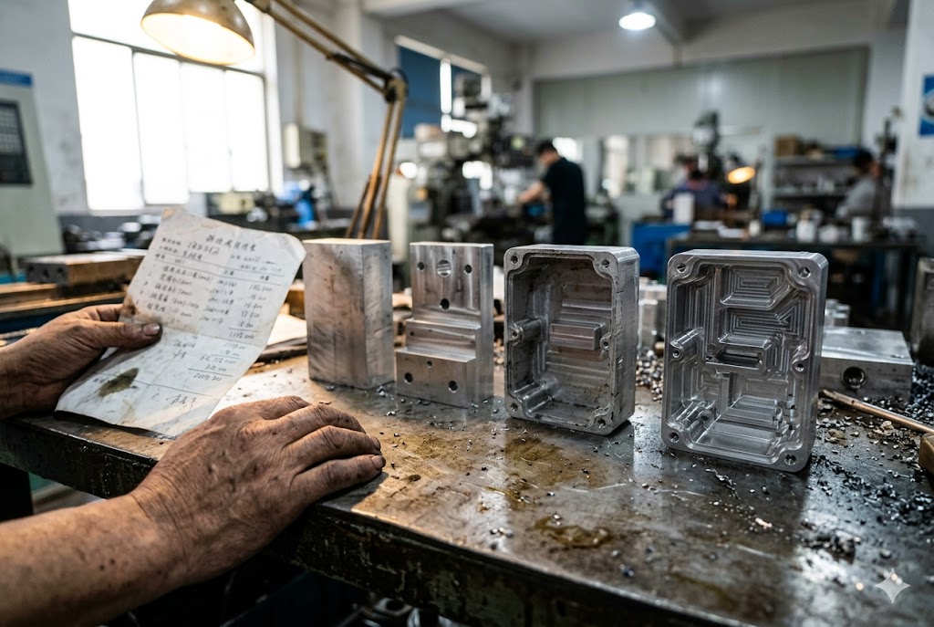
Every week, our team receives drawings from US and Canadian buyers who are shocked by the quotes they get back. The parts look similar on paper, but the prices are worlds apart. After years of sourcing and managing production across dozens of Chinese CNC shops, we know exactly why — and it almost always comes down to one thing: complexity.
Part complexity raises your CNC machining price through four compounding mechanisms: longer cycle time, higher setup and programming cost, more expensive machine type, and greater scrap and inspection overhead. These factors do not add linearly. A part that combines 5-axis machining, tight tolerances, thin walls, and deep pockets can cost 10–20 times more than a simple bracket.
Once you understand how these cost drivers work together, you can make smarter design decisions, ask better questions, and negotiate with more confidence. Let's break it down.
Which Design Features Make CNC Machining More Expensive?
When we review a new drawing with our engineering team, certain features immediately flag as high-cost. It is not guesswork — these patterns repeat across every factory we work with.
The design features that most increase CNC machining cost are: multiple setups, deep narrow pockets, undercuts, thin walls, and compound curved surfaces. Each one adds machine time, tooling cost, or scrap risk. When several appear on the same part, costs multiply rather than add.
Setups: The Hidden Time Killer
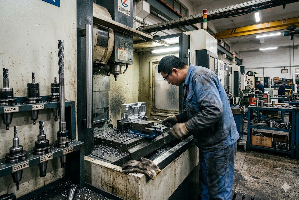
Every time a machinist repositions a part in the machine, the clock runs. Repositioning — also called a setup — involves unclamping the part, moving it, re-clamping it, and re-zeroing the machine coordinates. This takes 15 to 45 minutes of non-cutting time per setup.
A part that can be finished from one side in a single setup costs far less than a part that needs four sides machined in four separate setups. The overhead multiplies directly with the number of repositions.
Beyond the time cost, each new setup introduces positional error. The part is never re-clamped in exactly the same position. Features machined in setup 3 may not align perfectly with features machined in setup 1. On tight-tolerance parts, this accumulated error causes scrap — and scrap costs you money.
| Number of Setups | Approximate Time Overhead | Positional Risk |
|---|---|---|
| 1 | Baseline | Very Low |
| 2 | +25–40% | Low |
| 3 | +50–80% | Medium |
| 4+ | +100–150% | High |
Deep Pockets: The Tool Deflection Problem
Pockets are one of the most common features in mechanical parts. But depth matters enormously. The industry rule of thumb is a pocket depth-to-width ratio 1 of no more than 3:1. Beyond 4:1, the machinist must use a long-reach end mill, and long tools deflect under cutting forces.
To control deflection and prevent chatter, the machinist must cut more slowly — often reducing feed rates by 60 to 75%. A pocket that would take 5 minutes with a short stiff tool can take 15 to 20 minutes with a long-reach tool. That is a 3–4x increase in cycle time for a single feature.
Undercuts: When Standard Tools Cannot Reach
An undercut is any feature that sits beneath an overhanging surface. A standard tool approaching from above cannot reach it. The machinist must use a T-slot cutter, a lollipop cutter, or reorient the part entirely.
When specialty tooling cannot solve the problem, the part goes to EDM (Electrical Discharge Machining) 2. EDM is a separate secondary operation with its own setup charge, electrode cost, and lead time. Redesigning a part to eliminate undercuts — or splitting one complex part into two simpler halves that bolt together — can reduce total part cost by 30 to 50%.
Thin Walls: Vibration, Scrap, and Slow Cuts
Thin walls below 0.8 mm on metal (and 1.5 mm on plastics) vibrate as the cutting tool passes. This vibration — called chatter 3 — creates dimensional errors and poor surface finish. To reduce chatter, the machinist slows down, sometimes cutting at 50 to 70% of normal feed rate. Multiple light finishing passes replace a single efficient cut.
The result: cycle time increases 40 to 80% for thin-walled sections, and scrap risk rises sharply. Suppliers price in a quality contingency that shows up as a percentage premium in the quoted unit price.
| Wall Thickness (Metal) | Chatter Risk | Feed Rate Reduction | Cost Impact |
|---|---|---|---|
| >2.0 mm | Very Low | 0% | Baseline |
| 1.0–2.0 mm | Low | 10–20% | Minor |
| 0.8–1.0 mm | Medium | 30–50% | Moderate |
| <0.8 mm | High | 50–70% | Significant |
How Do Tight Tolerances and Deep Cavities Change the Quote?
In our experience managing quality control across Chinese CNC suppliers, tolerance is the single most misunderstood cost driver. Buyers often apply tight tolerances across an entire drawing without realizing the exponential effect on price.
Tight tolerances and deep cavities raise CNC quotes because they demand slower cuts, more inspection passes, and sometimes climate-controlled machining environments. Moving from a standard ±0.1 mm tolerance to ±0.01 mm can double or triple the cost of an entire part, not just the affected feature.
The Tolerance Cost Curve Is Not Linear
Most engineers understand that tighter tolerances cost more. Few realize how steeply that curve rises. Standard tolerance of ±0.1 mm is built into every CNC machine's baseline capability and carries no premium. Tighten to ±0.05 mm and you add 10 to 20% to the affected feature's cost. Move to ±0.02 mm and you add 30 to 60%. Drop below ±0.01 mm and the entire part cost can double or triple.
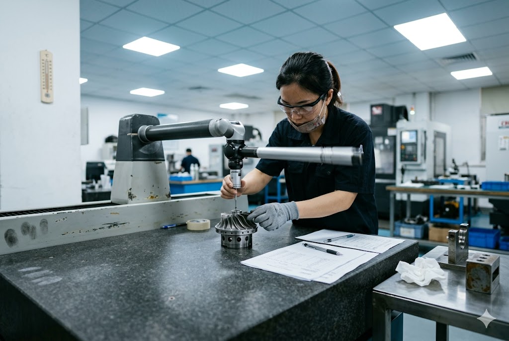
Why? Because sub-±0.01 mm work requires a climate-controlled machining environment (temperature changes cause metal to expand and contract, shifting dimensions), in-process gauging after every pass, multiple finishing passes at very slow speeds, and 100% CMM (Coordinate Measuring Machine) inspection 4 on every piece rather than statistical sampling.
| Tolerance Level | Premium Over Baseline | Inspection Method |
|---|---|---|
| ±0.1 mm (standard) | 0% | Sampling |
| ±0.05 mm | +10–20% | Sampling |
| ±0.02 mm | +30–60% | Increased sampling |
| ±0.01 mm | +80–150% | 100% CMM |
| <±0.01 mm | +100–200% | 100% CMM + climate control |
The Global Tolerance Mistake
The most common and expensive drawing error we see is applying tight tolerances to every surface on a part. Engineers often leave the default tight tolerance in their CAD template, or they apply it globally "to be safe." In practice, only mating surfaces — the faces, bores, and shafts that contact another component — need tight tolerances. Cosmetic surfaces, clearance holes, and non-contact faces can hold ISO 2768-m (medium) standard 5, which is far easier and cheaper to machine.
When every feature on a 30-feature part has a ±0.02 mm callout, the machinist must slow down for every single feature, and the inspector must measure every single surface. Relaxing tolerances on the 20 non-critical features can cut inspection time alone by 40 to 60%.
Deep Cavities and Cavity Aspect Ratio
Deep cavities — enclosed pockets with significant depth — compound the tolerance problem. A deep cavity forces a long-reach tool, which deflects more, making it harder to hold tight tolerances in the first place. The machinist must take lighter cuts, make more passes, and still accept higher dimensional variation than a shallow feature.
If your drawing calls for a deep cavity and a tight tolerance on its floor or sidewalls simultaneously, the machinist is fighting two problems at once. Suppliers handling this work factor in both the extended cycle time and a scrap risk premium. The quote you receive reflects this stacked difficulty honestly.
CAM Programming: The Hidden NRE Cost on Complex Parts
Before a single chip is cut, an engineer must convert your 3D CAD model into machine-readable toolpaths. This is CAM programming 6, and it scales steeply with geometric complexity. A simple prismatic bracket might take 30 to 60 minutes to program. A part with compound curves, multiple setup orientations, and 5-axis motion may require 6 to 12 hours of expert CAM work.
On a prototype or small first order, this programming time is entirely your cost. There is no amortization across other customers. On repeat orders, the program is reused and this cost disappears — which is why the unit price on your second or third order drops noticeably even when the part has not changed.
Can I Simplify My Part Design Without Affecting Function?
This is the question our sourcing team asks on every new project — and in our experience, the answer is yes more often than buyers expect. Most complex features exist because of habit or template defaults, not because the function genuinely requires them.
Yes, most parts can be simplified without losing function. The most impactful changes are: replacing sharp internal corners with standard fillet radii, widening narrow pockets to fit shorter stiffer tools, consolidating angled features to reduce setups, and relaxing tolerances on non-mating surfaces. These changes cost nothing in CAD and save money on every order.
Sharp Internal Corners: An Avoidable Cost
Internal corners on pocketed features cannot physically be machined as perfect right angles. A rotating end mill always leaves a radius equal to its own radius. When a drawing specifies a sharp internal corner with a 0 mm radius, the machinist must use a very small tool (which is slow, fragile, and expensive) or perform a secondary EDM operation.
Specifying a corner radius that matches a standard end mill tool size 7 — typically R1, R2, R3, R4, or R6 mm — allows the machinist to use a full-size, rigid tool at full speed. This single change can reduce cycle time on a pocket feature by 20 to 40%.
Pocket Width: Match Your Tool Library
Narrow pockets force long-reach tools. Wide pockets allow short, stiff tools. If you can design your pocket to be at least 3x the diameter of a standard end mill (6, 8, 10, or 12 mm are common), the machinist can use a standard tool at full speed without deflection concerns.
Review your pocket widths against standard tool diameters before finalizing your drawing. A 9 mm wide pocket that you widen to 12 mm may look nearly identical in the assembly but cuts machining time for that feature by half.
Consolidating Angled Features
Some parts have two or three angled faces machined in different orientations. Each orientation requires a separate setup. Consolidating similar angles — changing 12° and 15° features to a common 13° if function allows — can eliminate an entire setup and its associated time and error.
Splitting Monolithic Parts
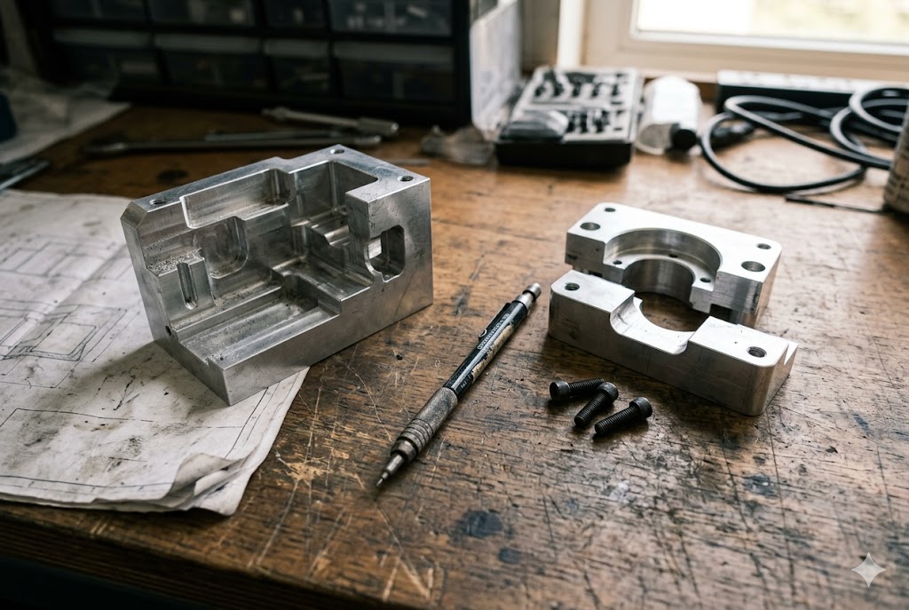
Sometimes the most cost-effective design decision is to split one complex part into two simpler ones that are joined by screws or pins. A monolithic part requiring 5-axis machining 8 and EDM work may cost $180 per piece. The same geometry split into two 3-axis parts joined by two M4 screws might cost $45 total. The assembly step adds one minute of labor. The math is obvious.
The question to ask your engineer: "Is this one part because function requires it, or because we always drew it that way?"
How Can I Ask Suppliers for Cost-Saving Design Feedback?
We have seen buyers leave 30 to 40% savings on the table simply because they never asked. Most Chinese CNC suppliers have capable engineers who can spot DFM issues — but they will not volunteer that feedback unless you ask directly and clearly.
To get useful cost-saving design feedback from a CNC supplier, share your CAD model and drawings early, ask specifically for a DFM (Design for Manufacturability) review, and request a breakdown of which features drive the most cost. Clear, specific questions get clear, specific answers.

Ask Early, Not After the Quote
The best time to request design feedback is before you finalize the drawing — ideally when you share the RFQ. At this stage, changes are free. After the quote is accepted and production is scheduled, even small design changes trigger re-programming costs, fixture changes, and schedule delays.
A simple sentence in your RFQ email makes a significant difference: "Please review the attached drawing and flag any features that significantly increase cost or risk. We are open to design changes if they do not affect function."
Ask for a Feature-by-Feature Cost Breakdown
A lump-sum quote tells you nothing useful. Ask for a breakdown by cost category:
| Cost Category | What It Covers | Your Leverage |
|---|---|---|
| Material | Raw stock, waste | Material substitution, near-net-shape blanks |
| Setup & Fixtures | Repositioning time, fixture build | Reduce setups, simplify geometry |
| Cycle Time | Actual cutting time | Simplify features, relax pocket depth |
| Tooling | Specialty tools, short-life tooling | Eliminate undercuts, standardize radii |
| Inspection & QC | CMM time, sampling vs 100% | Relax non-critical tolerances |
| CAM Programming | NRE engineering time | Reuse on repeat orders, simplify geometry |
When you see which category dominates, you know where to focus your DFM effort. If setup cost is 40% of the total, reducing setups is your highest-leverage change. If inspection is 25%, tolerance relaxation on non-critical features pays off fastest.
Frame Your Request as a Partnership
Buyers who frame DFM requests as a collaborative exercise get better responses than buyers who treat it as an adversarial negotiation. Our team has found that the most productive conversations start with: "We want this part to be manufacturable at volume. What would you change if this were your design?"
Experienced CNC engineers will tell you things your own engineers may not have considered — because they see hundreds of drawings per year and recognize patterns that desk engineers miss. A thorough DFM (Design for Manufacturability) review 9 early in the process is the single highest-leverage action available before production begins.
What to Watch Out For
Not all feedback is genuine DFM. Some is upselling. Be specific: ask for changes that reduce your unit cost, not changes that require more expensive machines or services. A supplier recommending 5-axis machining when 3-axis with an additional setup is adequate may be optimizing for their own margin, not your cost.
Compare DFM feedback from two or three suppliers. Consistent recommendations across multiple shops are almost always genuine. One-off suggestions that only benefit the recommending supplier deserve scrutiny.
Conclusion
Part complexity is the biggest hidden variable in your CNC import cost. Understanding how setups, tolerances, pocket geometry, and machine type interact gives you real leverage — in your design decisions, your RFQ process, and your supplier conversations. Over-specified tolerances across non-critical surfaces remain among the most overlooked drivers of unnecessary machining cost 10 — and fixing them requires nothing more than a drawing revision.
Footnotes
1. Explains how pocket depth-to-width ratios drive tool deflection and CNC cost escalation. ↩︎
2. Overview of Electrical Discharge Machining: how spark erosion removes material for complex geometries. ↩︎
3. Explains machining chatter: causes, effects on surface finish, and how to reduce vibration. ↩︎
4. Guide to CMM inspection: how coordinate measuring machines verify dimensional accuracy on CNC parts. ↩︎
5. Comprehensive breakdown of ISO 2768 tolerance classes and when to apply medium standard on drawings. ↩︎
6. Explains CAM software: how it converts 3D CAD models into CNC toolpath instructions. ↩︎
7. CNC design guidelines covering standard end mill sizes, pocket ratios, and wall thickness minimums. ↩︎
8. Full guide to 5-axis CNC machining: capabilities, single-setup advantages, and cost considerations. ↩︎
9. Explains DFM principles, cost-reduction benefits, and how early design reviews lower production expenses. ↩︎
10. Details five hidden cost categories when over-specifying tolerances, with real production cost multipliers. ↩︎



