 Skip to main content Skip to footer
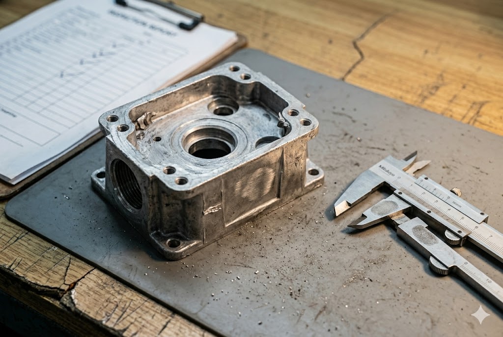
Every year, we see buyers receive first-article samples that warp, sink, or crack — not because the factory made a mistake, but because the wall thickness was wrong from day one on the drawing.
Wall thickness design directly controls whether your die cast part is manufacturable. Uniform walls between 0.8mm and 5mm for aluminum allow consistent fill and cooling. Uneven or oversized walls cause porosity, sink marks, and warping. Fix wall thickness before your supplier cuts steel, or you will pay for it twice.
There is a lot to unpack here. Let's go through each key question so you can walk into your next DFM review with a clear picture.
Can Uneven Wall Thickness Increase the Defect Risk in My Part?
When our team reviews customer drawings before quoting, wall thickness variation is the first thing we check — it tells us immediately how hard this part will be to produce consistently.
Yes, uneven wall thickness significantly increases defect risk. Sections that vary in thickness cool at different speeds. This creates differential shrinkage, warping, sink marks, and residual stress. These defects are predictable and preventable at the design stage, but expensive to fix after tooling is cut.
Why Cooling Rate Is Everything
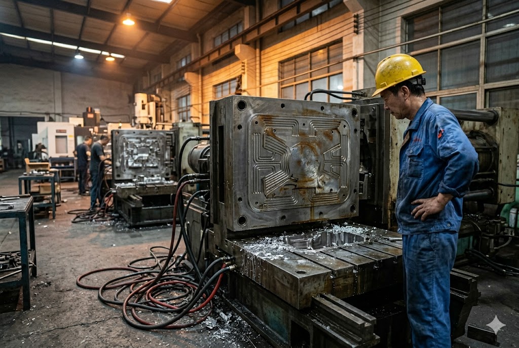
Molten metal enters the die cavity under high pressure 1 and must fill every corner before solidifying in a controlled, uniform way. When wall thickness varies, thin sections freeze first. Thick sections are still liquid. As the thick section cools, it contracts — but the surrounding solid material resists that contraction. The result is internal stress, surface sink marks, and in severe cases, cracking.
This is not a supplier process problem. It is a geometry problem. No process adjustment fully compensates for a design that violates basic thermal physics.
The Most Common Defects Caused by Uneven Walls
| Defect | Root Cause | Where It Appears |
|---|---|---|
| Sink marks | Thick section contracts after surface solidifies | Opposite face of a boss or rib |
| Warping | Differential shrinkage across the part | Flat panels, lids, covers |
| Porosity | Slow cooling creates coarse grain and voids | Inside thick walls, blind bosses |
| Cold shuts | Thin wall freezes before cavity fills | Narrow ribs, thin flanges |
| Residual stress cracking | Locked-in stress from uneven cooling | Near abrupt thickness transitions |
Abrupt Transitions Are the Worst Offender
Where wall thickness must change — and sometimes it must — the transition needs to be gradual. A tapered or filleted transition with a length equal to at least three times the thickness difference allows molten metal to flow progressively into the heavier zone. An abrupt step change creates a turbulent flow front that traps gas right at the junction. That trapped gas becomes porosity 2, which is invisible on the surface but catastrophic under cyclic load.
We have reviewed drawings from buyers who used a hard step from 1.5mm to 5mm in the same part. Every sample from that tool had a void cluster right at the step. The fix required recutting the tool — a cost that would have been zero if the transition had been addressed on the drawing.
Large Flat Surfaces Warp More Than You Expect
Large flat panels with uniform thickness are still at risk. Any slight cooling asymmetry across that flat face — caused by uneven die temperature, gate position, or ejector pin layout — creates a bowing moment. There is no structural feature to resist it. The panel warps after ejection.
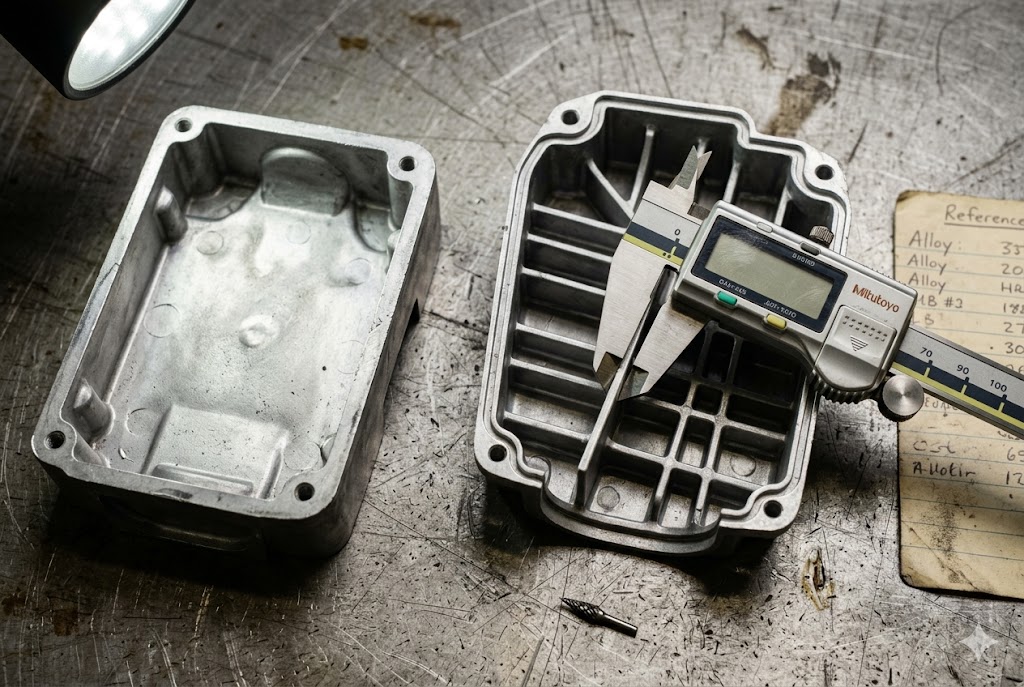
The fix is simple: add a shallow rib grid or a slight crown to the panel. This interrupts the flat geometry, stiffens the section, and masks minor flatness variation that is inherent in the casting process. This is a routine design move that most experienced engineers know — but many drawings arrive at Chinese factories without it.
How Do Thick Sections Affect Porosity, Shrinkage, and Cost for Me?
In our experience managing die casting projects for export, thick sections are the single biggest hidden cost driver — buyers rarely anticipate this when they first submit a drawing.
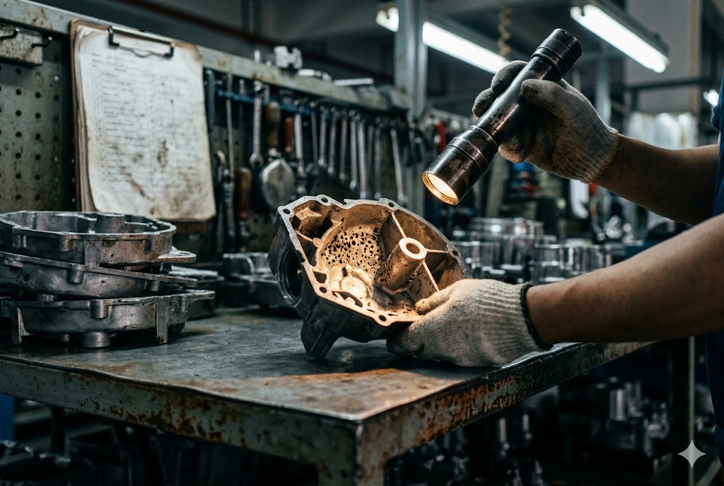
Thick sections in die cast parts slow cooling, increase cycle time, and raise per-part cost by 15–25% or more. They also produce internal porosity and shrinkage voids that are invisible to visual inspection but fail under load. Coring out thick sections is nearly always the right answer.
The Alloy-Specific Wall Thickness Window
Each alloy has hard limits. Going outside these limits in either direction creates problems that cannot be fixed in production.
| Alloy | Minimum Wall Thickness | Maximum Recommended Wall | Common Applications |
|---|---|---|---|
| Aluminum (ADC12, A380) 3 | 0.8–1.2 mm | 5 mm | Structural brackets, housings, covers |
| Zinc (Zamak 3, 5) 4 | 0.3 mm | 4 mm | Small precision parts, connectors |
| Magnesium (AZ91D) 5 | 0.6–1.0 mm | 4 mm | Lightweight structural parts |
Below the minimum, the metal freezes before the cavity fills. You get misruns — short shots where the part is simply incomplete. Above the maximum, the metal cools too slowly. The outer skin solidifies while the core is still liquid. As the core contracts, it pulls material inward, creating internal shrinkage voids 6.
How Thickness Drives Your Per-Part Price
Cooling time scales roughly with the square of wall thickness. A wall that is twice as thick takes four times as long to cool, not twice as long. Cycle time is the primary driver of die casting cost per part.
Going from 2.5mm to 5mm wall thickness in aluminum raises cooling time by 15–25%. That directly raises the price your Chinese supplier quotes per piece. If your program runs 50,000 parts per year, that cost premium is permanent and compounds over the program life.
Most buyers request extra wall thickness as a safety margin. In die casting, that instinct costs money without adding strength — because the thicker wall introduces porosity that reduces the effective strength of the material anyway.
The Correct Fix: Coring and Ribs
Coring out a thick boss or pad with a pocket removes the bulk material that causes porosity and slows cooling. The residual wall should be at least 1.5mm for aluminum. The cored pocket depth should not exceed five times its minimum width without a supporting rib — otherwise the core pin deflects under injection pressure and the resulting hole comes out tapered or off-center.
Ribs are the right way to add stiffness. A rib network achieves the same bending stiffness as a thickened wall with a fraction of the material. NADCA-recommended rib proportions 7:
| Rib Dimension | Recommended Value |
|---|---|
| Base thickness | 60–100% of nominal wall |
| Maximum height | 5× nominal wall thickness |
| Draft angle per side | 1–3° |
A rib that follows these proportions cools quickly, ejects cleanly, and adds stiffness without introducing the porosity and cost of a thick wall.
Should I Adjust My Design Before My Supplier Starts DFM Review?
Our engineers review dozens of drawings each month before sending them to factory partners for DFM. The drawings that arrive already cleaned up — with walls within spec, transitions tapered, and bosses cored — move through DFM in days. The ones that don't can stall for weeks.
Yes, you should audit your wall thickness design before submitting for DFM review. Catching violations early costs nothing. Fixing them after tool steel is cut costs thousands of dollars and weeks of delay. Review your drawing against alloy-specific thickness limits and NADCA guidelines before your supplier touches the file.
What a Pre-DFM Wall Thickness Audit Looks Like
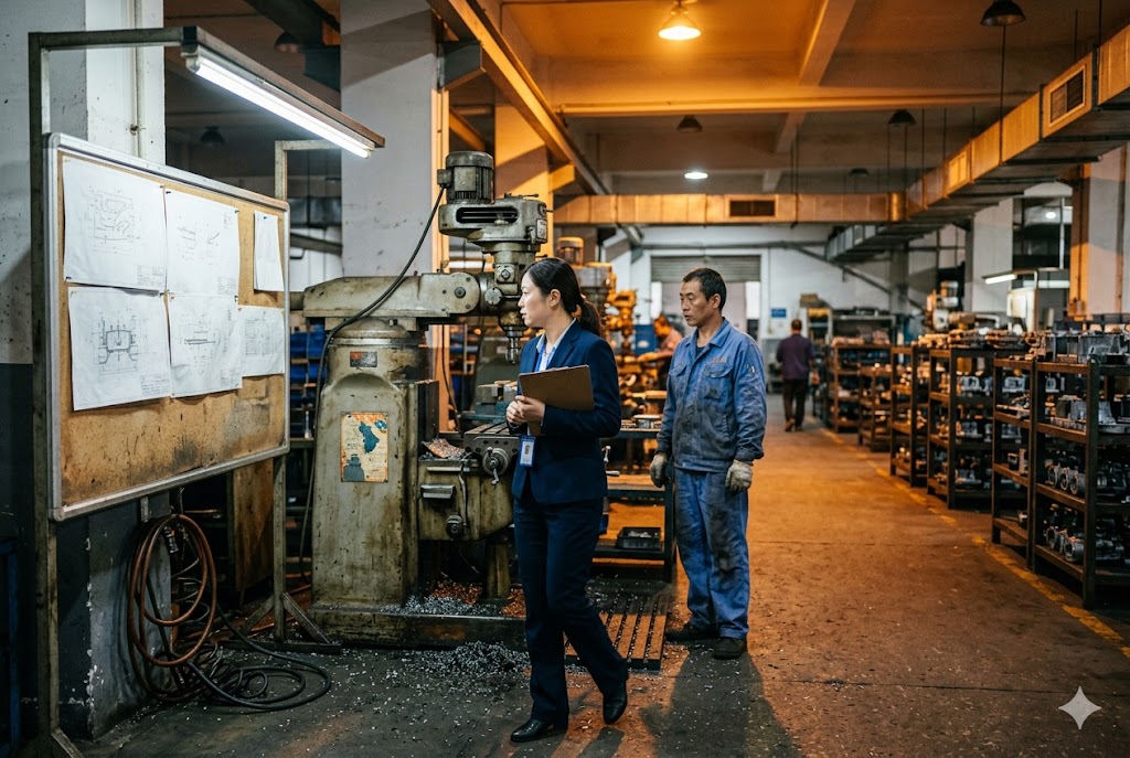
You do not need a full engineering team to do this. A basic check covers five items.
Five Things to Check Before Submitting Your Drawing
1. Identify your thickest section. Is it above 5mm for aluminum? If yes, can it be cored? If the boss or pad is structural, can it be converted to a cored boss with a 1.5mm residual wall?
2. Identify your thinnest section. Is it below 0.8mm for aluminum? Thin ribs and flanges are the usual offenders. If the feature is cosmetic, can it be thickened? If it is functional, can it be a machined feature added after casting?
3. Map all wall thickness transitions. Are any transitions abrupt steps? If yes, add a taper or fillet with a transition length of at least three times the thickness difference.
4. Check all bosses and mounting pads. Is the boss wall thickness equal to or greater than the surrounding nominal wall? If yes, reduce it to 60–80% of the nominal wall or core it out.
5. Check large flat panels. Is any flat surface larger than roughly 100mm × 100mm without a rib or crown? If yes, add a shallow rib grid or a slight dome.
Why This Matters for Suppliers in China Specifically
Not every factory in China runs a formal design for manufacturability 8 process. Lower-tier suppliers — the kind often found through sourcing platforms without direct qualification — will tool up exactly what the drawing shows. They do not flag thickness violations. When the first samples arrive with sink marks and warping, the supplier often attributes the defects to process variation or material quality rather than design root cause.
Making DFM review a contractual deliverable — with written sign-off on wall thickness compliance against NADCA standards — before tool steel is cut is the most effective protection you have. It also creates accountability: if a supplier signs off on a wall thickness audit and the samples still show sink defects at that location, the root cause conversation is much shorter.
| Pre-DFM Action | Cost if Done Before Tooling | Cost if Done After Tooling |
|---|---|---|
| Add taper to wall transition | Zero (drawing change) | $500–$5,000 tool modification |
| Core out thick boss | Zero (drawing change) | $1,000–$8,000 tool modification |
| Add rib to flat panel | Zero (drawing change) | $500–$3,000 tool modification |
| Thicken underspec thin wall | Zero (drawing change) | $500–$2,000 tool modification |
What Wall Thickness Range Is More Realistic for My Die Casting Project?
When clients ask us to validate a design before we place orders with our factory partners, wall thickness range is always part of that conversation — it determines not just quality but also which factories can realistically run the part.
For most aluminum die casting projects, a wall thickness range of 1.5mm to 4mm is both manufacturable and cost-effective. Zinc allows thinner walls down to 0.3mm. Staying within alloy-specific limits while minimizing thickness variation across the part produces the most consistent, lowest-cost result.
Practical Ranges by Alloy and Part Size
The limits in the table above are theoretical minimums and maximums. In practice, most production parts should target the middle of the range to allow for process variation, die wear over tool life, and dimensional drift through a production run.
| Alloy | Practical Target Range | Avoid Below | Avoid Above |
|---|---|---|---|
| Aluminum ADC12 / A380 | 1.5–3.5 mm | 0.8 mm | 5 mm |
| Zinc Zamak 3 / 5 | 0.5–2.5 mm | 0.3 mm | 4 mm |
| Magnesium AZ91D | 1.0–3.0 mm | 0.6 mm | 4 mm |
Why Dimensional Consistency Across a Run Depends on This
Wall thickness uniformity affects more than first-article samples. It affects dimensional consistency through an entire production run. Here is why.
A die heats up as production continues. Thick sections in the die take longer to reach thermal equilibrium than thin sections. This means the die expands unevenly through the early part of the production run. Parts made in the first 50 shots may be dimensionally different from parts made at shot 500, even with no change in machine settings.
A part with non-uniform walls will show this thermal drift more severely because the thick sections amplify the uneven heating effect. The first-article sample passes inspection. Mid-run and end-of-run parts drift out of tolerance. This defect only appears in statistical process control 9 data — not in a single first-article approval — and it surprises buyers who approved the first sample.
The Rib Solution Revisited
If your design currently has walls above 4mm for structural reasons, the rib solution 10 is almost always the correct path. A part with 2mm nominal walls and a well-designed rib network will:
- Cool faster and more uniformly
- Produce lower per-part cost due to shorter cycle time
- Weigh less, reducing material cost per shot
- Hold tighter dimensional tolerances across a production run
- Eject cleanly with less risk of sticking or drag
The weight reduction alone often pays for the engineering time to redesign the rib network. For a part running at 50,000 units per year, reducing shot weight by 15% through ribbing rather than solid walls reduces aluminum material cost permanently.
What This Means When You Source From Vietnam vs. China
Our Vietnam operation handles overflow and tariff-sensitive programs. The same wall thickness rules apply regardless of country — the physics of die casting do not change. However, some Vietnam factories have less experience with thin-wall aluminum parts below 1.2mm. If your design requires walls approaching the minimum, confirm your Vietnam supplier's capability with sample data from existing parts, not just verbal assurance.
Conclusion
Wall thickness is not a detail — it is the foundation of a manufacturable die cast part. Get it right on the drawing, make DFM sign-off contractual, and your first samples will be close. Get it wrong, and no factory in China or Vietnam can fix it for you after the tool is cut.
Footnotes
1. Overview of high-pressure die casting process, pressures, fill speeds, and design implications. ↩︎
2. Comprehensive guide to die casting defects, including porosity types, root causes, and prevention strategies. ↩︎
3. Comparison of A380, ADC12, and A360 aluminum die casting alloys for different design requirements. ↩︎
4. Guide to Zamak zinc alloys, including Zamak 3 and 5 properties, castability, and application selection. ↩︎
5. Technical data sheet for magnesium AZ91D alloy, covering composition, mechanical, and thermal properties. ↩︎
6. Nine root causes of shrinkage porosity in high-pressure die casting, with design and process solutions. ↩︎
7. Official NADCA product specification standards covering rib design, tolerances, and die casting guidelines. ↩︎
8. Principles and checklist for design for manufacturability (DFM) applied to casting and other processes. ↩︎
9. ASQ definition and overview of statistical process control methods for monitoring manufacturing quality. ↩︎
10. Die casting DFM best practices including rib design, uniform walls, and draft angles for cost reduction. ↩︎



