 Skip to main content Skip to footer
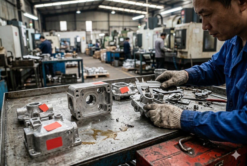
Every year, we see purchasing managers send RFQs to Chinese suppliers with drawings that were never reviewed for die casting feasibility. The result is always the same: delayed tooling, surprise costs, and parts that fail inspection on arrival.
Die casting design limitations include draft angles, wall thickness rules, undercut restrictions, and parting line placement. Understanding these constraints before you send your RFQ prevents tooling rework, reduces defects, and protects your landed cost when sourcing custom mechanical parts from China.
These are not small details. Each one can kill your project timeline or your margin. Read on and we will break each one down clearly.
How Do Wall Thickness, Draft Angles, and Undercuts Affect My Design?
When we review customer drawings before quoting, these three issues appear more than any others. They are also the three most likely to cause expensive surprises after the tool is already cut.
Wall thickness, draft angles, and undercuts directly control your tooling cost, part quality, and production yield. Aluminum die casting requires walls between 1.2mm and 5mm, draft angles of at least 0.5° per side, and each undercut adds $1,500 to $5,000 or more to your tool cost.
Wall Thickness Rules You Cannot Ignore
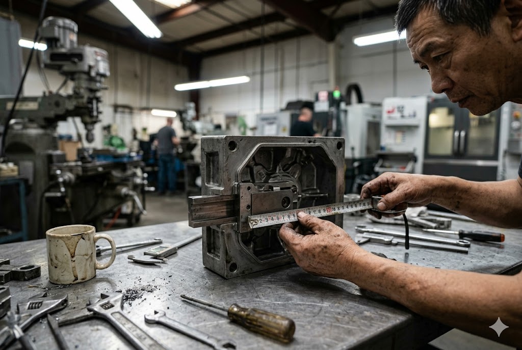
Uniform wall thickness is one of the most important rules in die casting. Our engineers flag this on almost every new drawing we receive.
For aluminum, the practical range is 1.2mm to 5mm. For zinc, walls can go as thin as 0.3mm. The problem is not just minimum thickness. It is consistency.
When one section of your part is 2mm thick and an adjacent section is 7mm thick, you have a problem. The thick section traps gas during solidification. The result is shrinkage porosity 1 — voids inside the part that are invisible to the eye but catastrophic under mechanical load.
Abrupt transitions also cause warping. The thin section cools fast. The thick section cools slowly. The part pulls itself out of shape after ejection. No secondary operation fixes warped aluminum cheaply.
| Material | Minimum Wall | Maximum Recommended | Risk Above Maximum |
|---|---|---|---|
| Aluminum | 1.2 mm | 5 mm | Shrinkage porosity, warping |
| Zinc | 0.3 mm | 4 mm | Gas entrapment, sink marks |
| Magnesium | 1.0 mm | 4 mm | Hot cracking, porosity |
Draft Angles Are Not Optional
Every vertical wall that runs parallel to the direction the die opens needs a taper. This is called a draft angle 2. Without it, the part grips the die on ejection and tears.
The minimum for aluminum is 0.5° per side on interior walls and 1° per side on exterior walls. Textured surfaces need 2° to 3° or more. When a drawing arrives without draft, the supplier has two choices: return it for redesign, or build the tool anyway and produce parts with drag marks and torn edges. A good supplier returns it. A cheap one builds it and you find out at inspection.
Draft must be designed in from the start. Adding it after the model is done often changes mating dimensions and requires engineering sign-off. This is one of the most common causes of RFQ delays we see from new customers.
Undercuts and Their Real Cost
An undercut is any feature that prevents the part from being pulled straight out of the die when it opens. To form an undercut, the tool needs a side-action 3, a lifter, or a loose core. Each mechanism adds complexity and cost.
| Undercut Solution | Typical Added Tool Cost | Lead Time Impact |
|---|---|---|
| Single side-action | $1,500 – $3,000 | +1 to 2 weeks |
| Complex side-action | $3,000 – $5,000+ | +2 to 4 weeks |
| Multiple axes | May require redesign | Unpredictable |
| Loose core | $500 – $2,000 | +1 week |
If your part has undercuts in multiple directions, some Chinese suppliers will simply not quote it. Others will quote a high price with a long lead time. The cleanest solution is to redesign the feature to eliminate the undercut before you send the RFQ.
What Features May Increase Tooling Complexity for My Project?
Before we send any drawing to a Chinese supplier for quoting, our team runs an internal DFM check. The features below consistently drive up tool cost and lead time.
Tooling complexity increases when your design includes enclosed internal cavities, holes deeper than six times their diameter, sharp internal corners, or features that straddle the parting line. Each of these either requires added tool mechanisms or forces secondary machining operations.
Internal Cavities and Hollow Sections
High-pressure die casting 4 cannot form fully enclosed internal passages. This is one of the biggest surprises for engineers who are familiar with sand casting or investment casting.
In sand casting, a sand core creates internal voids. Die casting has no equivalent for fully enclosed hollow sections. If your design has an internal coolant channel, a hollow structural tube, or an enclosed gallery, you have three options:
- Machine the passage in after casting
- Cast two halves and bond or fasten them together
- Redesign the part to eliminate the internal feature
Each option adds cost and time. Option 1 and 2 must be specified explicitly in your sourcing agreement. If you do not specify it, a Chinese factory may simply omit the operation and ship the part without the internal feature.
Hole Geometry Limits
Cored holes in die casting have practical limits. For aluminum, the minimum cored hole diameter is approximately 2mm. The depth should not exceed four to six times the hole diameter.
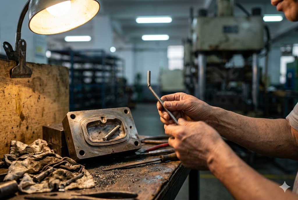
Beyond that depth, the core pin 5 — the steel rod that forms the hole — becomes too slender to handle injection pressure. It deflects or breaks. When it breaks, your tool is down and you are waiting for repair.
| Hole Diameter | Maximum Cored Depth | Alternative |
|---|---|---|
| 2 mm | 8 – 12 mm | Drill post-cast |
| 4 mm | 16 – 24 mm | Drill post-cast for deeper |
| 6 mm | 24 – 36 mm | Usually achievable as-cast |
| 8 mm+ | 32 – 48 mm | Core pin generally stable |
Holes deeper than these limits must be drilled after casting. Budget and specify this in your RFQ. Suppliers who skip this step and do not flag it will quote a lower price and deliver a part that fails your drawing requirements.
Sharp Internal Corners and Fillet Rules
Sharp internal corners cause two problems at once. In the part, they act as stress risers 6 — points where cracks start under load. In the tool, they concentrate fatigue from the thermal cycling of production. The tool steel cracks at sharp internal corners first.
NADCA guidelines specify a minimum internal fillet radius of 0.4mm. Our team recommends 0.8mm or larger wherever possible.
A competent Chinese supplier will return a drawing with square internal corners and ask for a design change. A low-cost supplier may build it as-drawn. The tool will show premature cracking within the first few thousand shots.
The Parting Line Problem
The parting line 7 is where the two halves of the die meet. It leaves a witness mark on every part. It also introduces the greatest dimensional variation across the part.
Any feature that straddles the parting line — a bore, a mating face, a precision locating surface — will have inconsistent dimensions across production runs. This causes chronic inspection failures. If your drawing has a tight tolerance on a feature that crosses the parting line, you will fail PPAP or first-article inspection routinely.
The rule is simple: keep critical dimensions and mating surfaces away from the parting line. Design the parting line location before you finalize the geometry, not after.
Can I Reduce Defects if I Simplify Certain Areas of My Design?
This is one of the most practical questions a purchasing manager can ask. Yes — geometry directly controls defect rate. Simpler geometry produces fewer defects, higher yield, and lower per-part cost.
Simplifying your die casting design reduces defects by eliminating gas traps, improving metal flow, and reducing tool wear. The highest-impact changes are smoothing abrupt wall transitions, removing unnecessary undercuts, and relocating ejector pins to non-cosmetic surfaces.
Where Defects Actually Come From
Most die casting defects trace back to three root causes: poor metal flow, differential cooling, and tool damage. Geometry drives all three.
Gas porosity forms when metal traps air during injection. Complex geometry with dead-end pockets and abrupt direction changes gives air nowhere to escape. Simplifying the flow path reduces this directly.
Shrinkage porosity forms in thick sections that cool last. The surrounding metal solidifies first and locks the thick section in place. As it shrinks, it pulls voids into itself. Uniform wall thickness eliminates most shrinkage porosity.
Warping results from uneven cooling. Thin sections cool fast, thick sections cool slow, and the part distorts. Consistent cross-section depth is the fix.
Ejector Pin Placement Is a Design Decision
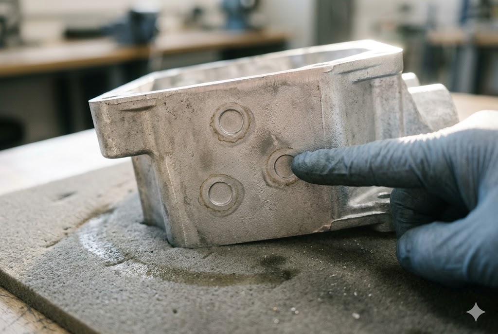
Every die cast part produced in China will have circular witness marks on one surface. These are ejector pin marks. They are unavoidable. What is avoidable is putting them on cosmetic or functional surfaces.
The designer controls where ejector pins land. If you do not specify this, the toolmaker will place them wherever it is mechanically convenient — often on visible faces or mating surfaces.
Specify ejector pin zones on your drawing. Mark surfaces where pins are acceptable and surfaces where they are not. This takes five minutes at the design stage and prevents weeks of tool rework after first article.
The Cost of Moving Ejector Pins After the Tool Is Cut
If you receive first-article parts and find ejector pin marks on a cosmetic surface, the fix is expensive. The toolmaker must weld the existing pin pocket, re-machine the surface, drill a new pocket in an acceptable location, and re-harden and polish the area.
This adds weeks of delay and thousands of dollars. It is entirely preventable with a single note on the drawing before the tool is built.
Design Simplification Checklist
| Design Element | Action to Reduce Defects | Impact |
|---|---|---|
| Abrupt wall transitions | Add gradual tapers between sections | Reduces warping and porosity |
| Dead-end pockets | Open or eliminate | Reduces gas traps |
| Unnecessary undercuts | Redesign geometry | Reduces tool cost and failure risk |
| Sharp internal corners | Add fillets ≥0.8mm | Reduces tool fatigue cracking |
| Ejector pin location | Specify on drawing | Prevents cosmetic damage |
| Parting line features | Move critical dims away | Reduces inspection failures |
What Design Limits Should I Understand Before I Send My RFQ?
Before we forward any customer drawing to a Chinese supplier for quotation, we check one more layer of details. These are the limits that determine whether a design is quotable at all — and whether the tolerances on your drawing match what die casting can actually deliver.
Before sending your RFQ, confirm that your drawing specifies NADCA tolerance tiers, that as-cast tolerances are acceptable for non-critical features, that design changes favor removing metal rather than adding it, and that all post-cast secondary operations are explicitly listed.

As-Cast Tolerances Are Coarser Than You Expect
This surprises many purchasing managers who come from a machined parts background. Die casting produces good tolerances — but not CNC tolerances.
NADCA standard linear tolerances 8 for aluminum start at approximately ±0.13mm for small features near the parting line. This degrades further as feature size increases and as the feature crosses the parting line.
If your drawing calls for ±0.05mm on an as-cast feature, no Chinese supplier can meet it without secondary machining. A supplier who quotes it without flagging this is either planning to machine it without telling you, or planning to ship non-conforming parts.
Tolerance Tiers Must Be Explicitly Called Out
NADCA classifies tolerances into standard and precision tiers. Standard tolerances are achievable as-cast. Precision tolerances require secondary operations.
If your drawing does not classify features by tolerance tier, Chinese suppliers will default to standard tolerances. Features requiring precision tolerances will be non-conforming on arrival.
| Tolerance Class | Achievable As-Cast (Aluminum) | Typical Application |
|---|---|---|
| Standard | ±0.13 mm (small features) | Non-mating, non-functional surfaces |
| Precision | ±0.05 mm or tighter | Bores, locating features, mating surfaces |
| Post-machine | ±0.01 mm or better | Bearing seats, threaded holes, sealing faces |
The One-Direction Rule for Design Changes
Die casting follows a simple asymmetry: removing metal from a tool is easy and cheap. Adding metal requires welding the tool, re-machining, and re-hardening — all of which weaken the die and add cost and delay.
This means the direction of your engineering changes matters. If you are not sure whether a wall is thick enough, start it thicker. If you are not sure a pocket is deep enough, start it shallower. After first-article inspection, you can open the tool to remove steel. You cannot easily close it to add steel.
This is not a minor point. We always advise customers to build this logic into their design for manufacturability 9 reviews before the drawing is released for tooling.
What Must Be Specified in Your RFQ
Before you send your drawing, confirm these items are clearly stated:
- Tolerance tier classification for every critical feature
- Secondary machining operations (drilling, tapping, milling) listed explicitly
- Ejector pin restricted zones marked on the drawing
- Parting line location agreed and shown
- Surface finish requirements with Ra values or visual standards
- Post-cast treatments (shot blasting, anodizing, powder coat) specified
If any of these are missing, the supplier will make assumptions. Those assumptions will not always match your requirements. Failing to specify them is also one of the leading reasons parts fail PPAP or first-article inspection 10 when they arrive.
Conclusion
Die casting design limits are not obstacles. They are rules. Know them before you send your RFQ, and you protect your tooling budget, your lead time, and your part quality from the start.
Footnotes
1. How unequal wall thickness causes shrinkage porosity in pressure die casting. ↩︎
2. Aluminum die casting design guide covering draft angles and ejection best practices. ↩︎
3. Wikipedia overview of undercuts in molding and how side-actions resolve them. ↩︎
4. NADCA FAQ explaining high-pressure die casting capabilities and process fundamentals. ↩︎
5. Die casting design guidelines covering core pin depth limits and hole geometry rules. ↩︎
6. Engineering guide to stress risers, fillets, and corner geometry in cast and machined parts. ↩︎
7. NADCA Design resource explaining parting line placement and its effect on tolerances. ↩︎
8. NADCA technical standards for die casting tolerances, design guidelines, and production specifications. ↩︎
9. Dynacast DFM FAQ on design-for-manufacturability principles applied to die casting. ↩︎
10. 1Factory guide to first-article inspection: what it covers, why it matters, and how it relates to PPAP. ↩︎



