Skip to main content Skip to footer

We machine Swiss-turned parts 1 to tolerances as tight as ±0.005 mm — then watch them fail first article after plating. Surface treatment changes dimensions. Most drawings never account for it.
Anodizing, nickel plating, and chrome plating all add measurable material to your part surfaces. Type II anodize grows each surface by 4–12 µm outward. Electroless nickel adds 5–25 µm uniformly. Hard chrome can add 25–250 µm with significant edge variation. On tight-tolerance Swiss-turned features, these values are not negligible — they are the difference between pass and fail.
Understanding each process and how it interacts with your dimensions is the only way to get usable parts the first time. The sections below break it down process by process, feature by feature.
How Do I Adjust My Machined Dimensions to Compensate for Plating Thickness and Still Meet Final Tolerances?
Our QC team sees this problem on nearly every new plated part we bring into production. The drawing specifies a post-finish diameter. The machinist hits the target. The plating goes on. The part is now oversized.
To compensate for plating, machine the pre-finish dimension undersize by the expected coating growth on that surface. For anodize, undersize each surface by 4–12 µm. For electroless nickel, undersize by 5–25 µm. For hard chrome, undersize by 25–250 µm — then plan for post-plate grinding on precision diameters because chrome buildup is non-uniform.
The 50/50 Rule for Anodizing
Type II anodizing 2 creates an oxide layer that grows in two directions simultaneously. Roughly half penetrates into the aluminum substrate. The other half builds outward. Total coating thickness per surface runs 8–25 µm. Outward growth per surface is therefore 4–12 µm.
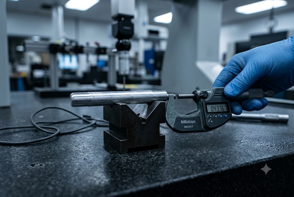
For a shaft diameter, outward growth happens on both sides. A 12 µm outward growth per surface adds 24 µm to the total diameter. If your final drawing calls for 25.000 mm, you must machine the pre-finish OD to approximately 24.976 mm under a standard Type II spec.
Type III hard anodize is more aggressive. Total coating runs 25–75 µm per surface, producing 12–37 µm of outward growth per surface. On that same 25.000 mm shaft, hard anodize at 50 µm total specification will push the finished diameter to approximately 25.050 mm unless you machine it undersize beforehand.
Alloy Matters More Than Most Buyers Realize
Here is something that does not appear on most datasheets: 7075-T6 aluminum 3 anodizes faster than 6061-T6 under the same bath parameters. Same current density, same time, same temperature — but 7075 produces more oxide growth and a harder, more dimensionally variable layer.
If your supplier machines 7075 to the same pre-finish allowance as 6061, the hardcoated parts will systematically overgrow. We have seen this cause consistent dimensional failures on the second production lot — right after the first-article sample (often machined from 6061 bar stock) passed without issue. The fix is to compare pre- and post-finish CMM data per lot and ensure your anodizing subcontractor adjusts bath time by alloy.
Electroless Nickel: The Most Predictable Process
Electroless nickel plating (ENP) deposits 5–25 µm per surface with a thickness uniformity tolerance of ±10% (minimum ±2 µm across all wetted surfaces). This predictability is its main engineering advantage. Because ENP is autocatalytic 4 rather than electrolytic, it reaches internal bores, blind holes, and threaded features at nearly the same deposit rate as external ODs.
That means you can apply a single pre-plate machining allowance across all surfaces simultaneously — external diameters, internal bores, and threads all grow by approximately the same amount. This makes ENP particularly well suited to Swiss-turned parts with complex geometry.
Hard Chrome: Pre-plan for Post-plate Grinding
Hard chrome 5 plating adds 25–250 µm per surface depending on the application. Unlike ENP, electrolytic processes concentrate current at edges, corners, and exposed ends. Localized buildup at those features runs 20–50% above nominal thickness. This edge-buildup effect means hard chrome is not a net-shape finishing process for precision diameters. Post-plate cylindrical grinding or lapping is typically required.
Budget for two operations: plate, then grind. Build that sequence into your lead time and your drawing revision history.
| Process | Coating per Surface | Outward Growth per Surface | Post-plate Grinding Required? |
|---|---|---|---|
| Type II Anodize | 8–25 µm | 4–12 µm | No (loose tolerances) |
| Type III Hard Anodize | 25–75 µm | 12–37 µm | Sometimes |
| Electroless Nickel (ENP) | 5–25 µm | 5–25 µm | Rarely |
| Hard Chrome | 25–250 µm | 25–250 µm (non-uniform) | Yes, for precision ODs |
| Decorative Chrome (over Ni) | 6–17 µm total | 6–17 µm | No |
Internal Features: Where Most Calculations Break Down
Bores and threaded holes behave differently from external diameters. Anodize closes a bore by the full coating thickness on each side — not the half-thickness that applies outward on an OD. A 10 µm coating growing inward on both sides of a bore removes 20 µm from the bore diameter. For a precision bore held to H7 tolerance 6, this is significant.
Electrolytic nickel and electrolytic chrome plate inconsistently or not at all in deep holes without auxiliary anodes. Only ENP reliably coats internal features. If your part has critical threaded holes or precision bores, specify ENP or plan for internal features to remain uncoated — and call that out explicitly on the drawing.
Which Plating Process Causes the Least Dimensional Impact on Tight-Tolerance Swiss-Turned Features?
When clients send us Swiss-turned parts with tolerances tighter than ±0.013 mm, we always steer the conversation toward process selection before surface selection.
Decorative chrome (0.8–2 µm chrome over 5–15 µm nickel undercoat) adds the least total material at 6–17 µm per surface, but it is limited to visual parts. For functional precision features, electroless nickel plating is the least dimensionally disruptive option: uniform deposition of 5–25 µm per surface with ±10% thickness control, including consistent coverage of internal geometry where electrolytic methods fail.

Ranking the Processes by Dimensional Predictability
Not all coatings are equal when it comes to dimensional risk. The question is not just how much material is added — it is how consistently and uniformly that material is applied across all surfaces of a complex Swiss-turned part.
| Process | Thickness Range | Uniformity | Internal Feature Coverage | Dimensional Risk |
|---|---|---|---|---|
| Decorative Chrome | 6–17 µm total | Moderate | Poor | Low (visual parts only) |
| Electroless Nickel (ENP) | 5–25 µm | ±10% (±2 µm min) | Excellent | Low |
| Type II Anodize | 8–25 µm | Moderate | Closes bores | Medium |
| Type III Hard Anodize | 25–75 µm | Variable by alloy | Closes bores | High |
| Hard Chrome | 25–250 µm | Non-uniform at edges | Poor in bores | Very High |
Why Electroless Nickel Wins for Precision Swiss Parts
ENP is autocatalytic. Deposition rate does not depend on current density or part geometry. That means a Swiss-turned component with undercuts, cross-holes, and threaded bores receives the same coating thickness on every wetted surface — the exposed OD, the bore ID, and the thread flanks all grow by approximately the same amount.
This is a meaningful engineering advantage. You can write a single pre-plate machining allowance and apply it globally across the part. No separate bore calculation, no anxiety about current shadowing in deep features.
ENP also offers a secondary benefit: phosphorus content in the deposit (typically 8–12% for high-phosphorus ENP) provides corrosion resistance comparable to hard chrome in many industrial environments without the hydrogen embrittlement risk inherent in electrolytic processes.
When Hard Chrome Is the Only Option
Functional wear surfaces — valve stems, hydraulic rod ends, tool shanks — sometimes require hard chrome because no other coating matches its hardness (850–1000 HV) and wear resistance. In those cases, dimensional management requires a different strategy:
- Machine the pre-plate diameter undersize by the minimum expected chrome deposit thickness.
- Plate to the high side of the chrome specification.
- Post-plate grind or lap the precision OD to final dimension.
- Verify diameter at three axial positions and both ends of the plated zone to catch edge buildup.
This two-step sequence adds cost and lead time. It is a known trade-off when hard chrome is specified for functional reasons.
The Hydrogen Embrittlement Risk You Cannot See at Incoming Inspection
Electrolytic chrome and electrolytic nickel introduce atomic hydrogen into the steel substrate during plating. This does not change part dimensions. It does not show up on CMM. But it causes delayed fracture under service stress in high-strength steel parts — particularly components with hardness at or above 40 HRC.
AMS 2759/9 7 and ASTM B849 8 both require a post-plate stress relief bake at 190–205°C within four hours of plating. We have audited Chinese plating subcontractors where this step was simply not performed unless the purchase order explicitly required it — and required a time-stamped furnace log as proof. If your Swiss-turned components are high-strength steel and will see tensile or bending loads in service, this is not optional.
Can a Chinese Swiss CNC Factory Manage Surface Treatment Subcontractors and Include Them in My Lead Time?
This is a question we get from every new client who has been burned by a missed ship date. The short answer: yes, a capable factory can manage subcontractors. But the key word is "manage."
A capable Chinese Swiss CNC factory can coordinate surface treatment subcontractors within a quoted lead time, but only if they have established supplier relationships, incoming inspection capability for plated parts, and a QC protocol that covers pre- and post-plate measurement. Without those elements, the subcontract step is a blind spot that delays shipments and produces untraceable dimensional failures.
How the Subcontract Chain Actually Works
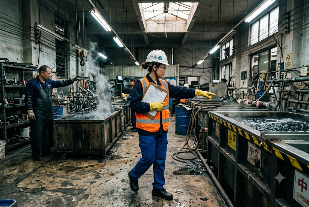
Most Swiss CNC shops in China do not operate in-house plating or anodizing lines. Surface finishing is subcontracted. The typical flow is:
- CNC shop machines parts to pre-plate dimensions.
- Parts are shipped to a plating subcontractor — often a small job shop with no dedicated quality system.
- Parts are plated and returned with a batch certificate of analysis (COA).
- CNC shop packages and ships to the client.
The structural problem is step 3. The plating subcontractor delivers parts with a batch COA stating coating type and nominal thickness. There is no per-part thickness measurement. There is no per-feature CMM data. The CNC shop receives the parts back and has no mechanism to confirm that coating thickness on each critical feature is within specification.
The Traceability Gap
We call this the subcontract traceability gap. It is structurally acute for surface finishing. The only way to close it is to specify per-feature thickness measurement as a contractual acceptance condition at the plating subcontractor level. This means:
- Coulometric testing or eddy-current measurement 9 on flat reference surfaces
- Cross-section verification on a sample basis for tight-tolerance features
- Minimum three measurement points per part, per lot
Those requirements must be written into the purchase order to the plating subcontractor — not just stated verbally. The data must travel back with the batch.
What to Ask a Factory Before You Place the Order
When evaluating whether a Swiss CNC factory can manage this subcontract step reliably, ask these questions directly:
| Question | What a Good Answer Looks Like |
|---|---|
| Who is your plating subcontractor? | Named facility, ideally audited or certified |
| How do you verify coating thickness on returned parts? | Specific instruments, measurement points, and frequency |
| Can you provide pre- and post-plate CMM data? | Yes, with sample size defined |
| Is post-plate bake performed on steel parts? | Yes, with furnace log available |
| How is subcontract lead time built into your quoted delivery? | Buffer time stated, not assumed |
If the factory cannot answer those questions with specifics, the subcontract step is unmanaged. That means dimensional failures and delays land in your lap, not theirs.
Our Approach When We Manage These Projects
When we oversee Swiss-turned projects that include surface treatment, we audit the plating subcontractor before the first production run. We require a pre-plate machined sample with CMM data, a post-plate sample with thickness verification data, and a reconciliation showing that the growth is within the allowance specified on the drawing. That package is the acceptance condition for releasing the first production batch. We also build subcontract transit and re-inspection time explicitly into the quoted lead time — not as a footnote, but as a named line item.
How Do I Specify Plating Requirements on My Drawing to Avoid Ambiguity with the Supplier?
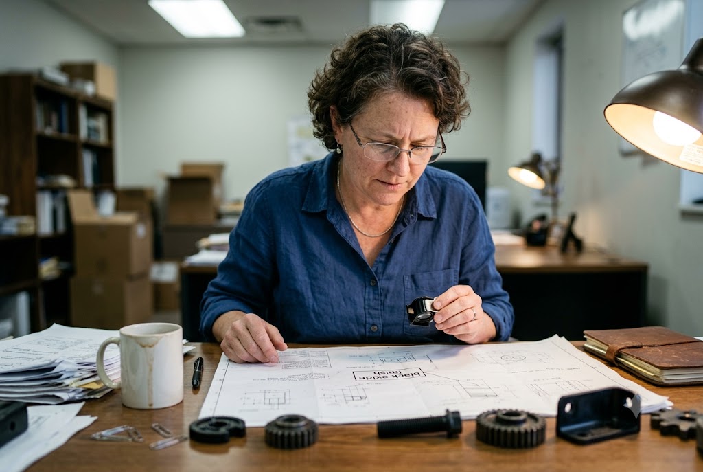
After reviewing drawings from US buyers for many years, our engineers see the same ambiguity problems on nearly every plated part drawing we receive. A complete plating callout prevents an entire class of supplier errors.
A complete plating specification on a technical drawing must state: the coating type and standard (e.g., "Electroless Nickel per ASTM B733") 10, the thickness range per surface, the pre-finish machined dimension as a manufacturing note, and the post-finish dimension as the governing inspection callout. Drawings that specify only the post-finish dimension with no pre-finish target are the leading cause of first-article rejection after surface treatment.

The Dual-Dimension Drawing Note
The single most effective change you can make to a plated part drawing is to add a dual-dimension note: one pre-finish machined target and one post-finish inspection dimension. They are different numbers. Both need to be on the drawing.
Here is a practical example for a 12.000 mm OD shaft with electroless nickel at 15 µm per surface:
- Post-finish (governing): Ø 12.000 ± 0.010 mm
- Pre-finish machined (manufacturing aid): Ø 11.970 ± 0.005 mm
- Finish specification block: "Electroless Nickel per ASTM B733, Class 4, Grade B — 15 µm ± 2 µm per surface"
The machinist works to 11.970 mm. The inspector checks the finished part at 12.000 mm. The plater knows the target thickness. No ambiguity at any step.
Minimum Elements of a Complete Finish Specification Block
| Element | Example Callout | Why It Matters |
|---|---|---|
| Process and standard | Electroless Nickel per ASTM B733 | Defines the chemistry and acceptance criteria |
| Class or type | Class 4, Grade B (medium-phosphorus) | Defines hardness, corrosion resistance, and deposit properties |
| Thickness range | 15 µm ± 2 µm per surface | Bounds the dimensional growth calculation |
| Coverage area | All surfaces unless noted | Prevents misinterpretation on complex geometry |
| Post-plate bake | "Bake at 190°C for 3 hours per AMS 2759/9" | Required for steel parts ≥40 HRC |
| Inspection record | "Provide thickness COA per lot with 3-point measurement" | Closes the traceability gap |
Calling Out Exempted Features
Some features cannot accept coating. A press-fit bore that requires a specific interference value. A thread that must be free-running after plating. A sealing surface with a flatness requirement that coating would violate. These must be called out explicitly on the drawing with a flag note or a locally hatched zone marked "No Plate" or "Mask."
If you do not call them out, the plater will coat them. The plater is not wrong to do so — an unmarked surface is a platable surface by default. The ambiguity is on the drawing.
Pre-Finish Notes Protect You at First Article
When a plated part fails first-article inspection, the first question is always: was the part machined undersize before plating, or was it machined to the final dimension? Without a pre-finish note on the drawing, there is no way to answer that question from the documentation. You cannot tell whether the failure is a machining error or a plating-thickness error. You have no data to request a corrective action from either party.
A pre-finish dimension note costs nothing to add to the drawing. It creates a documented checkpoint that lets you isolate the failure mode the first time — before you are arguing with a supplier over who owns the scrap cost.
One Standard Reference Is Not Enough
Calling out "anodize per MIL-A-8625" feels complete. It is not. A standard reference alone does not specify thickness range, alloy-specific growth rate, pre-finish machined dimension, or exempted features. Without those elements, every supplier will interpret the callout differently, and first-article failures on tight-tolerance features are nearly certain.
The standard is the starting point. The thickness range, the pre-finish target, and the inspection requirement are the drawing's job to state.
Conclusion
Plating is not a cosmetic afterthought on Swiss-turned parts. It is a dimensional operation. Every process adds material — and on features held to ±0.013 mm or tighter, every micron counts. Know your process, calculate your allowance, write both dimensions on the drawing, and audit the subcontractor who actually runs the tank.
Footnotes
1. Overview of Swiss CNC machining capabilities and precision tolerances for turned components. ↩︎
2. Comparison of Type II and Type III anodizing under MIL-A-8625, including coating thickness and dimensional effects. ↩︎
3. Key differences between 7075-T6 and 6061-T6 aluminum including anodizing response and dimensional behavior. ↩︎
4. How autocatalytic ENP delivers uniform coverage on complex CNC geometries, including internal features. ↩︎
5. Hard chrome plating properties, hardness values (HV 940–1210), and industrial wear applications. ↩︎
6. Complete guide to H7 tolerance designation, bore fit standards, and tolerance values by diameter. ↩︎
7. AMS 2759/9E requirements for hydrogen embrittlement relief baking of plated steel parts. ↩︎
8. ASTM B849 specification for pre-treatments of iron or steel to reduce hydrogen embrittlement risk. ↩︎
9. Fundamentals of coulometric and eddy-current methods for measuring plating thickness on metal parts. ↩︎
10. ASTM B733 standard for electroless nickel-phosphorus coatings: classifications, thickness grades, and engineering applications. ↩︎