Skip to main content Skip to footer
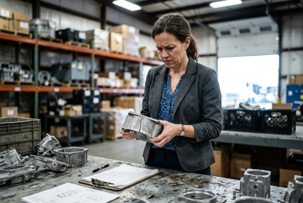
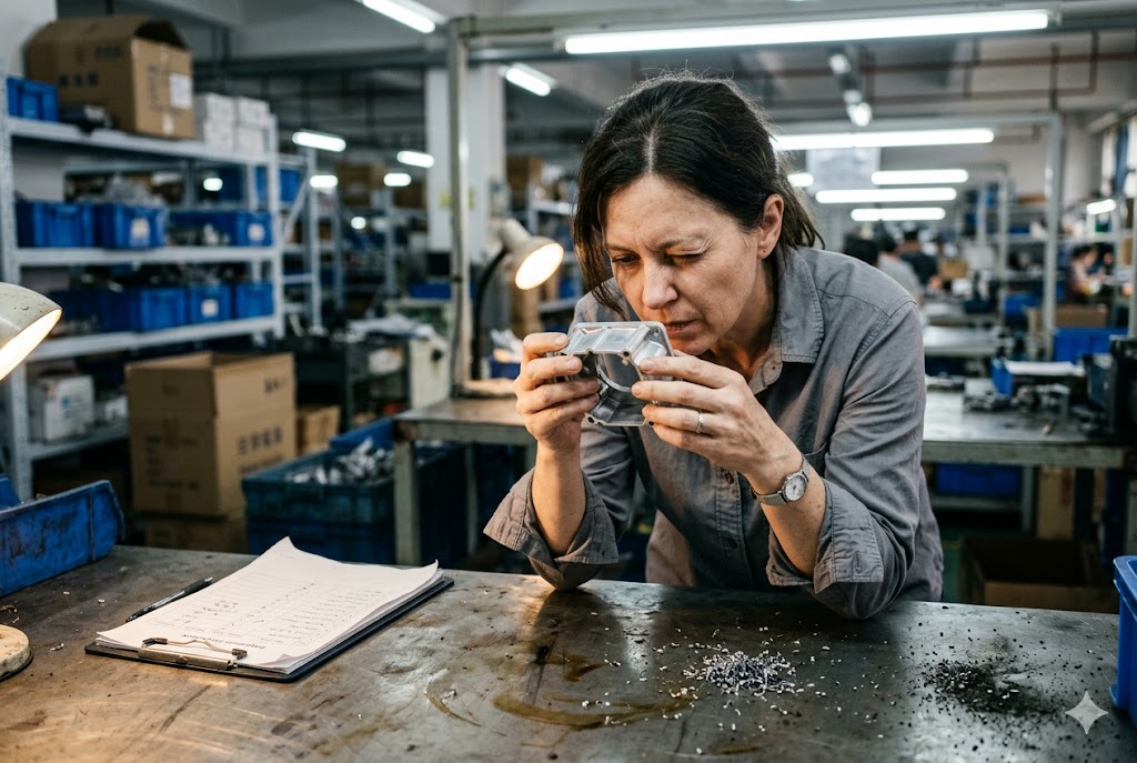
We see this every time a new client sends us a batch of failed parts — the surface looks clean, the dimensions check out on the first few pieces, and then production stops because the part cracked, leaked, or stripped a thread. The defect was already there before the parts left China.
Porosity, shrinkage, and flash are the three most common die casting defects that affect imported custom parts. Porosity reduces tensile strength by 10–30%, shrinkage creates structural weak points in thick sections, and flash causes assembly failures and safety risks. All three can be controlled with the right supplier process and acceptance criteria.
Understanding each defect before you place your order is the single most valuable thing you can do. The rest of this article explains exactly how.
When Do These Common Die Casting Defects Become Serious for My Application?
Every batch of die cast parts has some level of imperfection. The real question is not whether defects exist — it is whether they matter for what your part is doing.
A die casting defect becomes serious when it affects the function your part was designed to perform. Structural parts fail under load, sealed housings leak, and machined features lose dimensional integrity. The severity depends on defect type, location, size, and the load or environment the part will face in service.

Why Location Matters More Than Size
A small void in the center of a non-critical rib is very different from the same void sitting beneath a threaded boss that takes 25 Nm of torque. Our engineers have found that most field failures trace back not to large defects but to well-placed small ones.
Here is a simple way to think about it:
| Defect Location | Risk Level | Likely Failure Mode |
|---|---|---|
| Center of non-load-bearing wall | Low | Cosmetic only |
| Beneath a threaded hole | High | Thread strip, fastener failure |
| Inside a seal groove | Critical | Leak path, O-ring failure |
| At a stress-bearing boss or lug | Critical | Fracture under normal load |
| Near a machined mating surface | High | Dimensional loss after machining |
Structural Applications
Gas porosity 1 is the highest-risk internal defect for any structural part. It is invisible on the surface. You cannot catch it with calipers or a visual check at the dock. X-ray inspection or cross-sectioning is the only reliable way to find it. Even at just 2–3% porosity by volume, tensile strength 2 drops by 10–30%. A part can pass every visual and dimensional check and still be structurally compromised.
Shrinkage porosity 3 is equally dangerous in thick-walled sections. The voids are larger, irregular, and jagged-edged. Under tensile or fatigue loading, those jagged edges act as crack initiation sites. A part with shrinkage near a load-bearing boss will fail at a fraction of its designed load capacity — sometimes far below what your safety factor was supposed to protect against.
Sealed and Pressure-Tight Applications
Through-porosity is catastrophic here. When connected voids form a continuous path from one surface to the other, you have a direct leak path. No surface treatment fixes this. Impregnation can help, but it is a band-aid, and it has to be specified before production. If your part is a housing, manifold, or fluid channel that must hold pressure, through-porosity from a supplier running standard HPDC without vacuum assist is your single highest risk.
Secondary Machining Operations
This one catches many importers off guard. Porosity that is fully enclosed inside a casting is harmless — until your shop drills, taps, or mills into it. The moment a cutting tool breaks into a void, a benign internal defect becomes an open surface defect. It destroys thread continuity. It opens up a leak path in a sealing surface. It changes the dimension at exactly the feature you machined to tight tolerance. If your die cast parts receive significant secondary machining, you need to inspect for subsurface porosity before machining, not after.
Surface Finishing
Anodizing, electroplating, and powder coating all use liquid chemistry. That chemistry enters blind pores beneath the surface. After finishing, it bleeds back out. The result is peeling, fisheyes, corrosion pitting, and adhesion failure that appears days or weeks after receipt. By the time you see it, the supplier has probably shipped two more batches.
Can Some Porosity Be Acceptable Depending on How My Part Is Used?
When clients ask us this question for the first time, the honest answer surprises them: yes, porosity can be acceptable — but only when it is defined, located, and verified.
Some porosity is acceptable in die cast parts when the defect is below a defined size and density threshold, located away from functional features, and confirmed through agreed sampling and inspection methods. Acceptance depends entirely on the part's application, load conditions, and any post-processing operations.

Defining Acceptable Limits Before Production
The mistake most importers make is leaving porosity acceptance to the supplier's judgment. Suppliers will ship what they produce. Without a written standard, anything that does not visibly fall apart gets packed and sent.
You need to define three things:
- Maximum pore size — typically specified as a diameter in millimeters
- Maximum pore density — number of pores per unit area or volume
- Restricted zones — areas of the part where zero porosity or tighter limits apply
Use a drawing or 3D model to mark restricted zones. Common zones include threaded bores, sealing faces, press-fit areas, and any wall that will be machined.
Porosity Standards You Can Reference
Several industry standards provide a starting point:
| Standard | Scope | Typical Use |
|---|---|---|
| ASTM E505 4 | Reference radiographs for aluminum castings | Aerospace, automotive structural |
| ISO 10049 | X-ray reference images for aluminum alloy castings | General industrial |
| NADCA Product Standards 5 | Die casting quality specification | General die casting |
| Mil-STD-453 | Radiographic inspection of castings | Defense, high-reliability |
You do not need to apply aerospace-grade limits to a bracket that holds a cover panel. But you do need to apply some standard. Reference one of the above, then negotiate which porosity grade is acceptable for your part, zone by zone.
The Fully Enclosed Porosity Exception
Fully enclosed gas pores that sit far from any functional feature and will not be exposed by machining pose no meaningful risk in most industrial applications. This is the one case where porosity can genuinely be ignored. The critical condition is confirmed: the pores must be internal, sealed by surrounding metal, away from stress points, and your machining operations must not breach them.
If you cannot confirm all of those conditions, treat the porosity as a risk.
Vacuum-Assisted Die Casting
Standard high-pressure die casting (HPDC) inherently traps air during injection. Gas porosity in every batch is almost unavoidable without vacuum assist. Many Chinese foundries at the lower end of the price range do not have vacuum-assisted equipment. When we visit supplier factories, vacuum capability is one of the first things we check. Vacuum-assisted HPDC 6 reduces gas porosity by over 80% — it is not a minor process refinement. If your part has porosity-sensitive features, you should be specifying vacuum assist in your RFQ, not discovering its absence after first-article inspection.
How Should I Discuss Defect Limits With My Supplier Before Mass Production?
Most quality problems at the production stage were negotiable before tooling was cut. The difficulty is that many importers do not know what to ask, and many suppliers do not volunteer the information.
Discuss defect limits with your supplier by defining acceptance criteria in writing before tooling begins, using reference standards and marked drawings to specify restricted zones, and confirming the supplier's inspection capability for each defect type. Include defect limits in the purchase order and first-article inspection plan.

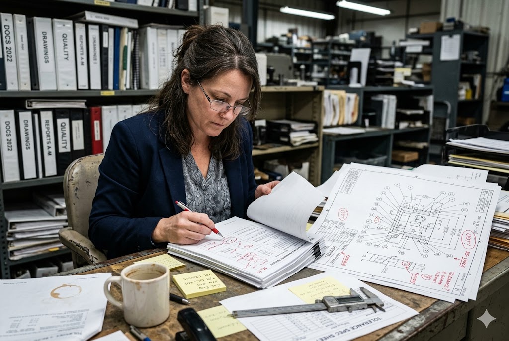
Start With the Right Documents
Before your first technical call with a supplier, prepare three documents:
- Marked drawing or 3D model — highlight restricted zones where tighter porosity or zero-flash limits apply
- Defect acceptance table — list each defect type, the maximum acceptable level, and the inspection method you expect the supplier to use
- First-article inspection (FAI) plan — list every feature to be measured and every defect to be verified before mass production approval
Send these with your RFQ. Suppliers who cannot respond to a written quality requirement are telling you something important about their process maturity.
Key Topics to Cover With Your Supplier
| Topic | What to Ask | Why It Matters |
|---|---|---|
| Porosity inspection method | Do you have X-ray capability on-site? | Confirms they can actually detect internal porosity |
| Mold flow simulation 7 | Did you run solidification simulation before cutting the tool? | Predicts shrinkage location; suppliers who skip this will have chronic shrinkage |
| Vacuum assist | Is this machine vacuum-assisted? | Determines baseline gas porosity risk |
| Flash control | What is your parting line tolerance? | Quantifies expected flash height |
| Die maintenance schedule | How many shots before scheduled die maintenance? | Flash and dimensional drift track die wear |
Flash: A Process Indicator, Not Just a Cosmetic Issue
Flash along parting lines is easy to trim. But flash appearing in a batch that was clean at first-article approval is a warning signal, not just a nuisance. It tells you the die is wearing, machine clamping tonnage has drifted, or the tool is not being maintained to schedule. Dimensional drift across all other features is likely happening at the same time.
Flash inside seal grooves destroys O-ring integrity. Flash inside threaded bores or mating features prevents proper assembly torque. These are not cosmetic problems. Define a maximum acceptable flash height for each zone of the part — typically 0.2–0.5 mm on non-critical faces and zero tolerance on sealing or mating surfaces.
The Porosity-Plus-Flash Warning Sign
When porosity and flash appear together on the same batch, it is a specific process signal. The supplier has likely increased injection pressure to overcome a filling problem or a cold-shut issue. The excess pressure blows metal through the parting line while simultaneously increasing air turbulence and entrainment inside the cavity. The result: more flash and more gas porosity in the same batch. Chasing one defect while creating two others. If you see this pattern, stop the batch and request a process review — do not accept corrective action promises without a written root cause analysis.
What Testing or Review Can Help Me Judge Whether These Defects Matter for Me?
You cannot manage what you do not measure. When we build inspection plans for clients importing custom die cast parts, we match the test method to the defect type and the risk level of the application.
The right testing approach combines X-ray or CT inspection for internal porosity, dimensional measurement for flash and critical features, and a structured first-article review before mass production approval. For pressure-sensitive parts, leak testing is mandatory. Test methods should be matched to defect type and application risk.

Matching Test Methods to Defect Types
Different defects require different detection methods. Visual inspection alone misses the most dangerous ones.
| Defect Type | Best Detection Method | Can Surface Inspection Find It? |
|---|---|---|
| Gas porosity (internal) | X-ray or industrial CT scan 8 | No |
| Shrinkage (thick sections) | X-ray, cross-section, CT scan | No |
| Through-porosity (leak path) | Pressure leak test or dye penetrant | Partially |
| Flash | Visual, CMM profile scan | Yes |
| Subsurface porosity (near surface) | Dye penetrant, X-ray | Partially |
| Cold shut | Visual, dye penetrant | Yes |
First-Article Inspection (FAI)
Every new tool and every new supplier relationship should start with a formal first-article inspection (FAI) 9 before mass production approval. An FAI for die cast parts should include:
- Full dimensional report against the drawing (every feature, not a sample)
- X-ray inspection of agreed cross-sections or views
- Material certification confirming alloy composition
- Hardness test if specified
- Surface finish measurement on critical faces
- Visual inspection for flash, cold shut, and surface defects
- Leak test if the part is a sealed housing or manifold
Do not approve mass production until the FAI is complete and every deviation is resolved or formally accepted. Rushing past FAI to meet a delivery schedule is the single most common reason clients come to us with a batch rejection problem three months later.
In-Process Quality Control
For higher-volume orders, FAI alone is not enough. We recommend specifying in-process controls that the supplier runs at defined intervals during production:
- Weight check of castings (a quick indicator of major porosity or fill variation)
- Dimensional spot check every 50–100 shots on critical features
- Visual inspection for flash and surface defects at the press
- X-ray on a defined sample frequency for porosity-sensitive parts
Pre-Shipment Inspection
A pre-shipment inspection by a third party — or by our team — catches problems before the container closes. For die cast parts, a pre-shipment inspection should cover dimensional sampling per AQL 1.0 10 or tighter, visual defect sampling, and review of the supplier's in-process records. If X-ray was specified, we verify the reports are present and review them.
Getting this step right means a defective batch gets identified in China, not at your dock in the US when your customer is waiting for parts.
Conclusion
Porosity, shrinkage, and flash each carry different risks depending on your part's function, location of the defect, and what happens to the part after casting. Define your acceptance criteria in writing before tooling begins, verify your supplier's inspection capability, and never skip the first-article inspection.
Footnotes
1. Overview of gas porosity in die casting: causes, types, and structural impact. ↩︎
2. Data on how 2–3% porosity can reduce aluminum die casting tensile strength by 10–30%. ↩︎
3. How shrinkage porosity forms in thick sections and initiates fatigue cracks in metal castings. ↩︎
4. ASTM E505 reference radiographs for grading discontinuities in aluminum and magnesium die castings. ↩︎
5. NADCA technical standards covering die casting quality specifications, tolerances, and design guidelines. ↩︎
6. How vacuum die casting removes cavity air to reduce gas porosity and improve mechanical properties. ↩︎
7. How solidification simulation predicts shrinkage hot spots before tooling is cut in HPDC. ↩︎
8. How industrial CT scanning detects internal porosity, shrinkage, and core shift in castings. ↩︎
9. What first-article inspection is, why it matters, and how it validates supplier process capability. ↩︎
10. AQL sampling standard used to determine sample sizes and accept/reject thresholds in pre-shipment inspections. ↩︎