 Skip to main content Skip to footer

We have seen drawings arrive at our sourcing desk with nothing but a tolerance block and a material callout — no roughness symbol, no Ra value, no finish note. Every time, the result is the same: the parts come back looking different from what the buyer expected, and no one is technically wrong.
To define surface roughness correctly on CNC parts ordered from China, always specify Ra values in micrometers using ISO 1302 symbols placed directly on each controlled surface. Add a general note in the title block — such as "Unspecified surfaces: Ra 3.2" — to cover all remaining faces. This removes ambiguity and gives your Chinese supplier a clear, measurable target.
Most drawing problems are not design problems. They are communication problems. The sections below will walk you through each piece of the puzzle.
What Surface Finish Standards Should I Use?
Our team processes drawings from buyers across North America every week, and the mismatch between drawing conventions and shop-floor expectations is one of the most common friction points we encounter in our export work.
For parts manufactured in Chinese machine shops, use Ra in micrometers (µm) with the ISO 1302 surface texture symbol. China's national standard GB/T 1031 maps directly to ISO, so Ra is universally understood on the shop floor. Avoid microinch (µin) units on ISO-referenced drawings to prevent dangerous unit misreading.

Why ISO 1302 and Ra?
Ra stands for Roughness Average. It measures the average deviation of a surface profile from its mean line. It is simple, repeatable, and well understood in every Chinese machine shop that runs ISO-compliant inspection.
China's GB/T 1031 standard 1 aligns with ISO 1302 2. When your drawing carries an ISO 1302 symbol with an Ra value, a Chinese quality inspector knows exactly how to measure it and what instrument to use. There is no translation step.
The risk of using non-ISO conventions is real. A drawing that uses µin units on an otherwise ISO-formatted document creates a 39× interpretation error. Ra 125 µin equals Ra 3.2 µm 3. If a supplier reads "125" and assumes µm — because every other number on the drawing is metric — your surface finish requirement collapses entirely.
Standard Ra Values and What They Mean
| Ra Value (µm) | Typical Process | Application |
|---|---|---|
| Ra 6.3 | Standard turning or milling | Non-functional surfaces, frames, covers |
| Ra 3.2 | Standard CNC finishing pass | General machined surfaces, default callout |
| Ra 1.6 | Optimized finishing pass | Mating faces, moderate fit surfaces |
| Ra 0.8 | Fine milling or grinding | Sliding contact, close-tolerance fits |
| Ra 0.4 | Grinding | Bearing bores, precision sealing surfaces |
| Ra 0.2 or below | Honing, lapping, polishing | Hydraulic components, optical surfaces |
The Title Block Note You Must Not Skip
Place a general note in the title block: "Unspecified surfaces: Ra 3.2 µm."
Without this note, Chinese suppliers apply their shop default. Shop defaults vary. Some shops run Ra 1.6 as default; others run Ra 6.3. You have no control over what you receive unless you specify it. This one line in the title block closes that gap.
Matching Specification to Process
Every Ra value implies a process. If you specify Ra 0.8 on a milled aluminum face, that is achievable with optimized finishing passes. If you specify Ra 0.8 on a hardened steel bore, that requires grinding. If your drawing does not indicate the expected process, a supplier quoting on milling alone will either price for grinding without telling you or omit grinding entirely and deliver a non-conforming part.
Match your callout to the process. If the process requires grinding, say so. If it requires polishing, say so. A clear drawing costs nothing to write. A non-conforming shipment costs significantly more to resolve.
How Does Roughness Affect Part Performance?
When we calibrate supplier quality requirements for our clients' parts, surface roughness is not a cosmetic checkbox. It is a functional variable that directly determines whether a part works, wears, seals, or fails.
Surface roughness affects sealing integrity, wear rate, fatigue life, and lubrication behavior. A surface that is too rough will leak or wear quickly. A surface that is too smooth may not retain oil and will also wear quickly. The correct Ra range depends entirely on the part's function.
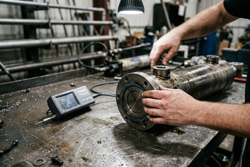
Roughness and Sealing Surfaces
For hydraulic or pneumatic sealing faces, the peak-to-valley height is the critical measurement — not the average. Two surfaces can share an identical Ra value but have completely different functional behavior if one carries isolated deep scratches while the other has uniform texture.
This is where Rz becomes necessary. Rz measures the average of the five highest peaks and five deepest valleys 4 in a measured length. For sealing surfaces, a single deep scratch invisible in the Ra reading can create a leak path. Specifying both Ra and Rz on sealing faces closes that gap.
Roughness and Bearing Surfaces
Bearing bores and sliding surfaces require a roughness range, not just a maximum. A callout of "Ra max 0.8 µm" technically permits a mirror-polished surface at Ra 0.1 µm. That surface will not retain lubricant. Wear accelerates. Bearing life drops.
The correct approach is a range: Ra 0.4–0.8 µm. This communicates both limits and the functional intent. The surface must be smooth enough to seal or contact evenly but textured enough to retain oil.
| Surface Type | Recommended Ra (µm) | Add Rz? | Notes |
|---|---|---|---|
| General machined surface | 3.2 | No | Standard shop output, no secondary ops |
| Mating flanges | 1.6 | No | Optimized pass, check flatness too |
| Hydraulic sealing face | 0.8 | Yes | Specify Rz max alongside Ra |
| Bearing bore | 0.4–0.8 (range) | Yes | Range enforces both limits |
| Sliding/contact surface | 0.8–1.6 | Optional | Retain lubricant film |
Roughness and Fatigue Life
On stressed parts, surface texture acts as a stress concentrator. Deeper valleys in the surface profile become initiation sites for fatigue cracks under cyclic loading 5. This matters most on shafts, connecting rods, and structural brackets with thin cross-sections. For fatigue-critical surfaces, Ra 0.8 or below is a common engineering requirement, and the drawing must say so explicitly.
Lay Direction: The Factor Most Buyers Forget
Ra and Rz measure texture amplitude. They say nothing about direction. The lay of a surface — the direction of tool marks — determines how a sealing contact ring forms around a gasket.
A face-turned sealing flange has circular lay. The tool marks run concentrically around the bolt circle. The gasket presses evenly against a ring of parallel ridges. Sealing is consistent.
The same flange milled flat has parallel lay. Tool marks run straight across the surface. A gasket pressed onto parallel grooves has potential leak paths perpendicular to the seal. The Ra reading may be identical. The functional result is different.
ISO 1302 provides lay symbols 6. Use them on any sealing or sliding surface. A supplier that passes Ra inspection but delivers the wrong lay direction has technically not violated the drawing — unless the drawing specifies lay.
Should I Include Ra Values in Drawings?
Our engineers have found, through hundreds of sourced parts projects, that the single most effective change a buyer can make to their drawing package is adding explicit Ra callouts. It reduces inspection disputes, clarifies supplier quotes, and eliminates the most common source of cosmetic non-conformance.
Yes — always include Ra values on your drawings. Place the ISO 1302 symbol directly on each surface that carries a specific requirement. Add a fallback general note in the title block for all unspecified surfaces. This gives Chinese suppliers a measurable, unambiguous target and removes the shop default as a variable.
Where to Place Ra Callouts
The ISO 1302 surface texture symbol 7 sits on the surface line, an extension line from the surface, or a leader line pointing to the surface. The Ra value appears inside or above the symbol. The rule is simple: if a surface has a specific roughness requirement different from the general note, it gets its own callout.
Do not place a single roughness note in the title block and assume it applies everywhere. Chinese suppliers will apply it to all unspecified surfaces — which is correct behavior — but any surface requiring a tighter or looser value must be individually called out.
Surface Finish Before and After Coating
This is a detail many buyers miss. Surface roughness specifications apply to the bare machined surface unless the drawing states otherwise. Anodizing does not smooth a surface 8. An Ra 3.2 aluminum face that is anodized becomes a colored Ra 3.2 face with fully visible tool marks.
If cosmetic appearance after anodizing matters, the drawing must specify either a pre-anodize bead blast or polish, or a required Ra value before the anodize note. The sequence matters. Write it on the drawing.
| Surface Treatment | Effect on Ra | Action Required |
|---|---|---|
| Hard anodize (Type III) | No improvement | Specify pre-anodize Ra or blasting step |
| Decorative anodize (Type II) | No improvement | Same as above |
| Electroless nickel plating | Slight smoothing (~10%) | Specify Ra before plating |
| Powder coating | Can fill minor texture | Specify Ra requirement after coating if critical |
| Passivation (steel/SS) | No measurable effect | Specify Ra before passivation |
Using a Roughness Range vs. a Maximum
For most surfaces, a maximum Ra is sufficient. "Ra max 3.2 µm" tells the supplier the surface must be at or below that value. Standard production practice will keep it well within range.
For bearing bores and sealing surfaces, use a range: "Ra 0.4–0.8 µm." This prevents over-polishing, which removes the texture needed for lubrication and reduces over-machining risk on soft materials. A range communicates functional intent far more clearly than a ceiling alone.
Why Explicit Callouts Protect You Commercially
When a surface finish dispute arises — and in B2B machining it does arise — the only document that matters is the drawing. If your drawing has no Ra callout, you have no contractual basis to reject a part on surface finish grounds. If your drawing carries an explicit Ra value on the surface in question, the inspector's profilometer reading either passes or fails. There is no argument.
How Can I Verify Surface Finish Quality?
At our factory visits and pre-shipment inspections, surface finish is one of the first things we check — and one of the most frequently under-documented in supplier inspection reports. Verification is not just about having a profilometer on the bench. It is about measuring the right surfaces, in the right direction, with the right instrument, and recording everything traceable.
To verify surface finish quality, require the supplier to measure Ra with a calibrated contact profilometer on all critical surfaces, measure perpendicular to the lay direction, and include the instrument ID, calibration date, measurement direction, and recorded value in the inspection report for each controlled surface.

Why Visual Inspection Is Not Enough
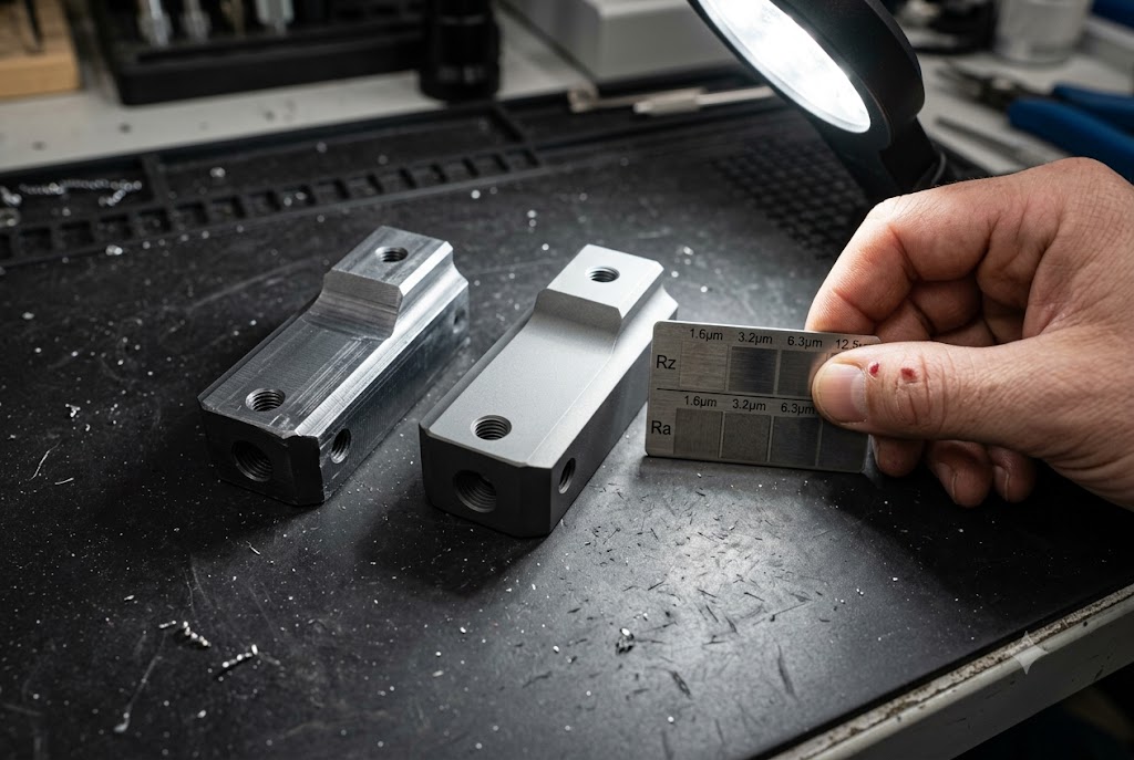
Visual comparison plates — the stamped metal cards with sample textures from Ra 0.4 to Ra 6.3 — are a fast shop-floor screening tool, not an acceptance method. Results vary by lighting angle, inspector experience, and comparison technique. The same surface can appear to match Ra 1.6 under bright overhead light and Ra 3.2 under diffuse side lighting.
Contact profilometers 9 trace a diamond stylus across the surface and compute Ra from the measured profile. They produce repeatable, documented results. For any surface where finish tolerance is tighter than Ra 1.6, visual comparison is insufficient for final acceptance.
Measurement Direction Matters
A surface roughness reading taken parallel to the lay direction can differ from a reading taken perpendicular to it by a factor of three on the same surface. This is not instrument error. It is physics. The ISO standard specifies that Ra measurements are taken perpendicular to the dominant lay direction.
If the drawing does not specify measurement direction and the supplier measures parallel to tool marks on a turned shaft, the recorded value may appear to pass while the cross-lay measurement would fail. Specify measurement direction on critical surfaces. Require it in the inspection report.
What to Require in the Inspection Report
An inspection report for surface finish should include, at minimum:
- Part number and revision level
- Surface identifier (matches drawing callout or annotation)
- Required Ra value (from drawing)
- Measured Ra value
- Measurement direction (perpendicular to lay, confirmed)
- Instrument make, model, and serial number
- Instrument calibration date and certificate reference
- Inspector name and date
Using Third-Party Inspection
For high-volume orders or tight-tolerance parts, third-party pre-shipment inspection at the supplier's facility is a practical safeguard. Our team arranges this as a standard service. The third-party inspector brings a calibrated profilometer, measures the agreed critical surfaces, and issues a report independent of the supplier's own QC team.
This is particularly valuable when the part involves both tight dimensional tolerances and controlled surface finish — for example, a hydraulic cylinder bore that must meet both roundness and Ra requirements simultaneously. An independent measurement eliminates any conflict of interest in the supplier's self-reported data.
Sampling Plan for Surface Finish
Not every part in a batch needs a full profilometer scan. A practical approach:
| Batch Size | Minimum Sample for Surface Finish |
|---|---|
| 1–10 pcs | 100% inspection on critical surfaces |
| 11–50 pcs | 20% random sample, min. 5 pcs |
| 51–200 pcs | 13% random sample, min. 10 pcs |
| 201–500 pcs | 8% random sample, min. 20 pcs |
| 500+ pcs | AQL 2.5 10 or as agreed in contract |
Document the sampling plan in the purchase order or quality agreement. A supplier that knows the inspection method and sample rate before production starts will plan process control accordingly.
Conclusion
Defining surface roughness correctly is not complicated, but it requires intention. Use Ra in µm, follow ISO 1302, add a title block fallback note, specify Rz and lay where function demands it, and require documented profilometer measurements. Do these things and your Chinese supplier has everything needed to deliver exactly what you drew.
Footnotes
1. GB/T 1031-2009: China's national surface roughness standard, specifying Ra parameters aligned with ISO. ↩︎
2. ISO 1302:2002: The international standard governing surface texture indication on engineering drawings. ↩︎
3. Ra/Rz/µin conversion chart showing that Ra 125 µin = Ra 3.2 µm and other key equivalents. ↩︎
4. Explains why Rz captures extreme peaks and valleys that Ra averages out, critical for sealing surfaces. ↩︎
5. Details how surface valleys act as stress concentrators and reduce fatigue life in CNC machined parts. ↩︎
6. Reference guide for ISO 1302 drawing indications, including lay symbols and their placement rules. ↩︎
7. Covers ISO 1302 surface finish symbols, machining capabilities, and cost implications for engineers. ↩︎
8. Explains how anodizing affects surface roughness Ra/Rz values and what to specify before coating. ↩︎
9. Overview of profilometer types, operating principles, and how Ra is computed from stylus traces. ↩︎
10. AQL sampling methodology guide explaining sample sizes, defect thresholds, and inspection levels. ↩︎



