 Skip to main content Skip to footer

Every week, our team reviews drawings from clients who have already had a bad shipment. The parts looked fine in photos. They passed the supplier's inspection. But they didn't fit. The root cause is almost always the same: critical dimensions were never defined clearly.
When sourcing CNC parts from China, you must identify three to five critical dimensions per part, box them on the 2D drawing, anchor them to physical datums, pair each with a specified inspection method, and submit a First Article Inspection plan before production begins. These steps prevent the most common and costly dimensional failures in Chinese machine shops.
If you skip these steps, you are relying on the supplier to guess what matters. Most of the time, they guess wrong. Here is how to do it right.
Which Dimensions Must Be Tightly Controlled?
When our engineers review a new part file, the first question we ask is: which surfaces or features directly affect how this part functions in the assembly?
The dimensions that must be tightly controlled are bearing seats, sealing faces, bolt-hole patterns, mating bores, and any surface that contacts another part in the final assembly. These are your Critical-to-Quality (CTQ) features. Everything else is non-critical geometry that does not need the same machining rigor or inspection cost.

What Makes a Dimension "Critical"?
A dimension is critical when an out-of-tolerance condition causes one of three outcomes: the part does not assemble, the part fails in service, or the part causes a safety issue. If none of those apply, the dimension is not critical.
Critical-to-Quality features 1 are the measurable characteristics that directly determine whether a product meets customer and assembly requirements. Here is a simple way to sort your dimensions into categories:
| Feature Type | Example | Critical? |
|---|---|---|
| Bearing seat bore | Ø 25.000 ±0.010 mm | Yes |
| Sealing face flatness | 0.005 mm | Yes |
| Bolt-hole true position | ⌀0.1 mm at MMC | Yes |
| External cosmetic radius | R2 ±0.5 mm | No |
| Overall part length | 150 ±0.5 mm | Usually No |
| Draft angle on non-mating surface | 2° ±0.5° | No |
Why Limiting CTQ Features Saves Money
Marking every dimension as critical is one of the most expensive mistakes a buyer can make. When our production team places an order with a factory, the shop floor allocates CMM time and gauging resources based on how many features require mandatory verification. If you flag 30 features, the factory either charges more or — more commonly — dilutes the inspection effort across all 30. Neither outcome helps you.
Limit your critical callouts to three to five per part. This keeps inspection cost predictable and forces the shop to apply their full attention to the features that actually control assembly success.
Reference Dimensions Are Not Inspected
One important distinction: reference dimensions, shown in parentheses on a drawing, are context information for the machinist. They are never inspected. Chinese shop floor staff — especially on dense drawings — will sometimes treat unlabeled critical dimensions the same way they treat reference dimensions. If it is not explicitly flagged, it may not be checked.
Always label your CTQ features. Never assume the machinist will infer importance from tolerance band size alone.
How Can You Communicate Critical Features Clearly?
Poor communication is the number one cause of dimensional failures we see in cross-border sourcing. The drawing arrives. The supplier reads it. And both parties believe they understood the same thing — until incoming inspection proves otherwise.
To communicate critical features clearly, enclose each CTQ dimension value in a box or pill-shaped callout directly on the 2D drawing, anchor every critical dimension to a physical and measurable datum, and specify the required inspection method for each feature in the drawing notes. These three steps remove ambiguity before the first chip is cut.
Use the Boxing Convention
In Chinese machine shops, a boxed dimension is the universally recognized signal for "this feature requires mandatory verification." It does not need a text note. It does not need a separate email. A box drawn around the dimension value on the 2D drawing tells the shop floor, the QC inspector, and the production manager that this number cannot be skipped.
This convention is understood across Mainland China, Vietnam, and Taiwan. Our team uses it on every drawing we forward to factories, regardless of whether the client originally used it or not.
Anchor to Physical Datums
This is the point most buyers get wrong. A dimension defined from a centerline, a CAD modeling plane, or an inferred mid-plane requires the supplier to make a geometric assumption during inspection. Different suppliers make different assumptions. Both can report conformance. Both can be technically right by their own interpretation. And your parts still won't assemble.
Anchor every critical dimension to a physical surface that exists on the actual part — a machined flat face, a finished bore shoulder, an edge that can be probed. If you use GD&T per ASME Y14.5 2, reference your datums in the same priority order used by the mating part in the assembly.
Here is the difference in practice:
| Datum Type | Measurable? | Supplier Assumption Required? | Recommended? |
|---|---|---|---|
| Physical machined face (Datum A) | Yes | No | Yes |
| Centerline of a bore | Derived, requires probing | Sometimes | With care |
| CAD modeling origin | No physical existence | Yes | No |
| Inferred mid-plane | Derived from two surfaces | Yes | No |
Specify the Inspection Method in the Drawing Notes
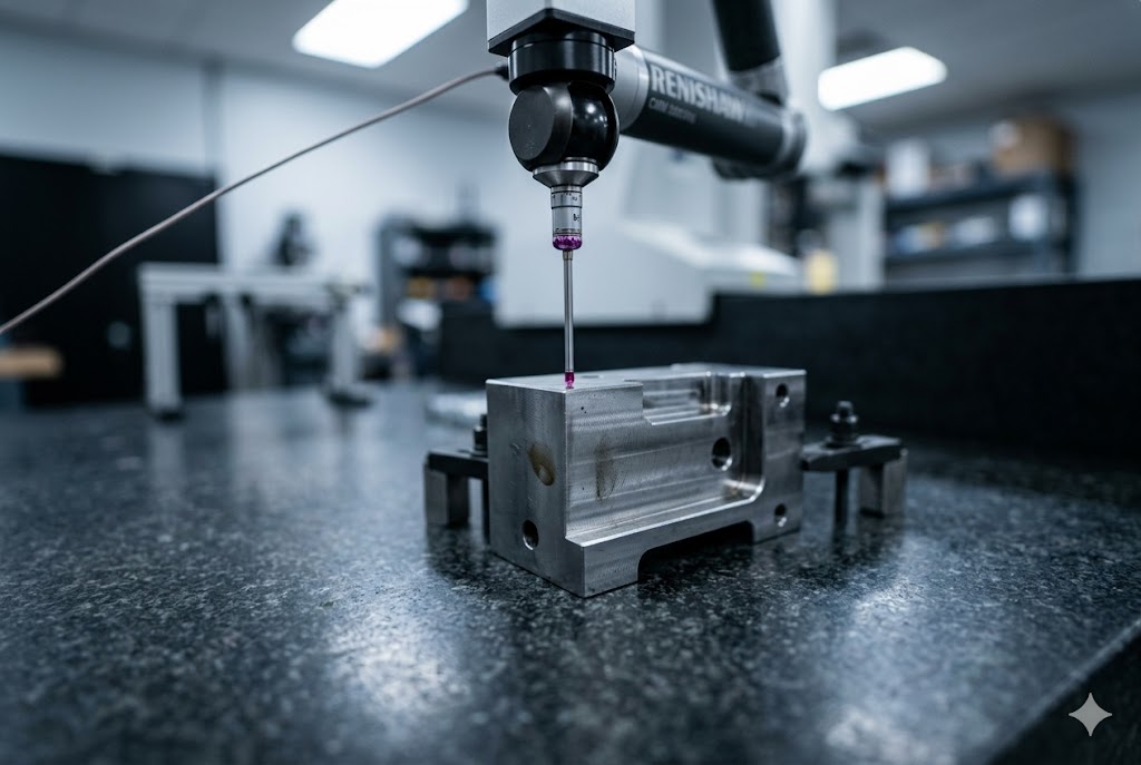
If you do not specify the inspection method, the supplier will default to calipers. Calipers are fast and cheap. They are also wrong for any feature that requires coordinate-based measurement. A bore true position deviation is invisible to a caliper. A flatness callout on a sealing face cannot be verified with a caliper. A bolt-hole pattern shift is missed entirely.
CMM inspection for CNC parts 3 uses a probe to collect precise three-dimensional measurements that manual tools cannot reliably produce. For each CTQ feature, add a short note to the drawing:
- CMM required
- Go/no-go gauge required
- Surface profilometer required
- Pin gauge required
These notes take 10 minutes to add. They prevent the most common failure mode in Chinese factory inspection: a feature that passes at the factory with the wrong instrument and fails at your incoming inspection with the right one.
Account for Surface Finishing
Anodizing and hard chrome add measurable material to aluminum parts 4, with build-up and penetration ratios that directly affect bore diameters and mating surfaces. A bore that is in tolerance before coating will be out of tolerance after coating if the drawing does not specify the measurement stage. The typical anodizing buildup is 0.005 to 0.025 mm per surface. On a bore with a ±0.010 mm bilateral tolerance, that is the entire tolerance band — consumed by a surface treatment the supplier did not know you wanted measured after.
State clearly on the drawing: "All critical dimensions apply after final surface treatment unless otherwise noted." Do not leave this to the supplier's interpretation.
Should You Highlight Key Tolerances Separately?
Yes. And a drawing alone is not enough. The drawing is a legal document. But it is not an operational guide for a QC team working under production pressure.
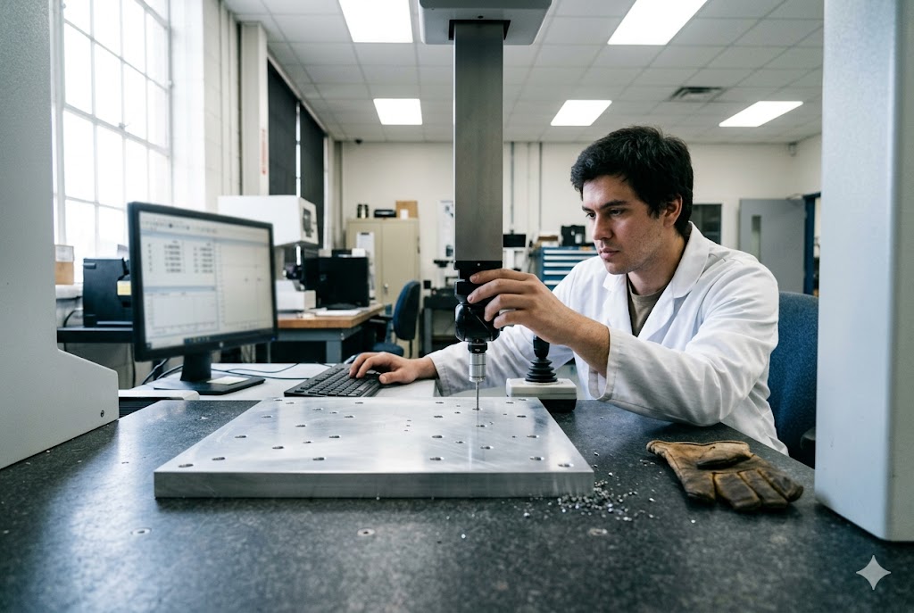
You should create a standalone First Article Inspection plan that lists only your critical dimensions, their tolerance bands, the required measurement instrument, and the acceptance threshold. This document separates your CTQ features from the full drawing and gives the supplier's QC team a prioritized checklist that survives drawing complexity and personnel changes.
What a Good FAI Plan Contains
A First Article Inspection plan structured per AS9102 5 requires documented, characteristic-by-characteristic verification of all design requirements before full production begins. It does not need to be complex — it needs to be clear and complete. Here is the structure we recommend for every new part:
| Column | Content |
|---|---|
| Feature ID | Unique reference number (e.g., CTQ-01) |
| Description | Plain-language feature name (e.g., "Main bore diameter") |
| Nominal Value | The target dimension (e.g., Ø 25.000 mm) |
| Tolerance | Bilateral or unilateral band (e.g., +0.000 / -0.020) |
| Inspection Instrument | CMM / go-no-go gauge / surface profilometer |
| Measurement Stage | Before or after surface treatment |
| Acceptance Threshold | Pass / fail criteria |
| Inspector Sign-off | Name and date |
This table goes to the supplier before production begins. Our team reviews the completed FAI report before any production parts are shipped. If a supplier returns an FAI with caliper readings on a true-position callout, we reject it and ask for CMM data. That single filter catches the majority of dimensional issues before they become a shipment problem.
Use True Position for Hole Patterns
Coordinate dimensioning of bolt circles is a common error in drawings sourced from North American designers and sent to Chinese factories. When you dimension each hole by X and Y coordinates from an origin, each hole can be individually within its positional tolerance while the pattern as a whole is rotated or shifted enough to prevent assembly.
Use GD&T true position callouts 6 referenced to the same datums used by the mating part. This makes the inspection condition assembly-equivalent. A hole pattern that passes true position inspection will fit. One that only passes coordinate inspection might not.
Thermal Expansion and Inspection Temperature
This issue appears most often with tight-tolerance aluminum parts. Our sourcing team has seen it cause borderline FAI failures several times. A bore machined to Ø 100.005 mm on a Chinese shop floor at 35°C will measure slightly larger when received in a 20°C metrology lab. For aluminum, the coefficient of thermal expansion is approximately 23 µm/m·°C 7, meaning the difference on a 100 mm bore across a 15°C temperature swing is about 0.035 mm. If your bilateral tolerance is ±0.010 mm, the part that passed at the factory fails at incoming inspection — not because the machining was wrong, but because no one controlled the inspection temperature.
If your part has tight-tolerance bores or shafts in aluminum or other high-expansion materials, add the inspection temperature to the drawing notes: "All critical dimensions measured at 20°C ±2°C per ISO 1 8."
How Does This Impact Inspection and QC?
Every decision you make on the drawing has a direct downstream effect on what gets inspected, how it gets inspected, and whether the inspection result is meaningful when the parts arrive at your facility.
Defining critical dimensions clearly transforms your supplier's QC process from a generic full-part check into a targeted, assembly-equivalent inspection. It also creates the contractual basis for rejecting non-conforming parts and requesting corrective action — without ambiguity on either side.

The Golden Sample Agreement
Before production begins on any new part, negotiate a golden sample agreement 9. This means: the supplier produces one or more sample parts, our team measures the critical dimensions, both parties sign off on the measured values, and the physical part is retained as the acceptance standard for all future production runs.
A golden sample does three things. First, it confirms the factory can actually hold the tolerances you need. If they cannot pass the golden sample stage, you know before you commit to production quantity. Second, it gives the supplier a physical reference to compare production parts against — more reliable than a drawing alone for features like surface finish, edge break, and general part geometry. Third, it survives personnel changes. If the engineer who read and understood your drawing leaves the supplier, the golden sample remains.
In-Production Quality Control
Incoming inspection at your facility is the last line of defense. But it is expensive and slow. The better strategy is to build control into the production process itself.
Our team offers in-production QC visits timed to when the first production articles come off the machine — before the full batch is run. At that stage, a dimensional non-conformance can be corrected with a tool offset or a fixture adjustment. After the full batch is complete, a non-conformance means rework or rejection.
The Cost of Getting This Wrong
Here is what poor critical dimension definition costs in practice:
| Failure Mode | Typical Cause | Typical Cost |
|---|---|---|
| Bore out of tolerance, no assembly | Undeclared CTQ, caliper inspection | Full batch rejection + rework lead time |
| Hole pattern shifted, no fit | Coordinate dim instead of true position | Rework or replacement production run |
| Bore fails incoming, passed factory | Wrong inspection instrument | Dispute, partial rejection, delay |
| Coating makes bore undersized | No measurement-stage callout | Rework or re-machining after stripping coating |
| Parts pass FAI, fail at production | No golden sample agreement | Ongoing incoming rejections across runs |
Each of these failure modes is preventable. None of them require expensive tooling changes or process upgrades at the factory. They all require better drawing communication and a structured QC agreement before production starts.
Supplier Accountability Without Conflict
When you define critical dimensions clearly — boxed on the drawing, anchored to physical datums, with specified inspection methods and a signed FAI plan — you create an unambiguous acceptance standard. If parts arrive out of tolerance, there is no room for interpretation disputes. The drawing says what is required. The FAI plan says how it must be measured. The golden sample says what an acceptable part looks like.
This protects both parties. The supplier knows exactly what they are committing to. You know exactly what you are entitled to receive. The conversation moves from "whose fault is this" to "here is the corrective action plan" — which is a much faster and more productive place to be.
Effective supplier quality control 10 depends on establishing agreed-upon physical references and documented inspection procedures before mass production begins, not after the first rejection arrives.
Conclusion
Define three to five critical dimensions per part. Box them on your drawing. Anchor them to physical datums. Specify the inspection method. Submit an FAI plan. Agree on a golden sample. These six steps cost almost nothing in time and prevent the most expensive problems in CNC sourcing from China.
Footnotes
1. Overview of Critical-to-Quality (CTQ) features, parameters, and their role in quality management. ↩︎
2. ASME Y14.5 is the authoritative standard for geometric dimensioning and tolerancing (GD&T) rules and symbols. ↩︎
3. How CMM inspection improves CNC quality control through three-dimensional coordinate measurement. ↩︎
4. Technical guide on how anodizing affects aluminum part dimensions through build-up and penetration. ↩︎
5. Comprehensive guide to the AS9102 First Article Inspection standard and documentation requirements. ↩︎
6. True position formula, MMC bonus tolerance, and worked examples for hole patterns per ASME Y14.5. ↩︎
7. Thermal expansion coefficient values for aluminum alloys in µm/m·°C with calculation formula. ↩︎
8. NIST peer-reviewed history and explanation of the 20°C standard reference temperature for dimensional inspection (ISO 1). ↩︎
9. What a golden sample is, why it matters, and how it aligns supplier and buyer before mass production. ↩︎
10. How importers use golden samples and QC procedures to minimize defects when sourcing from China. ↩︎



