 Skip to main content Skip to footer
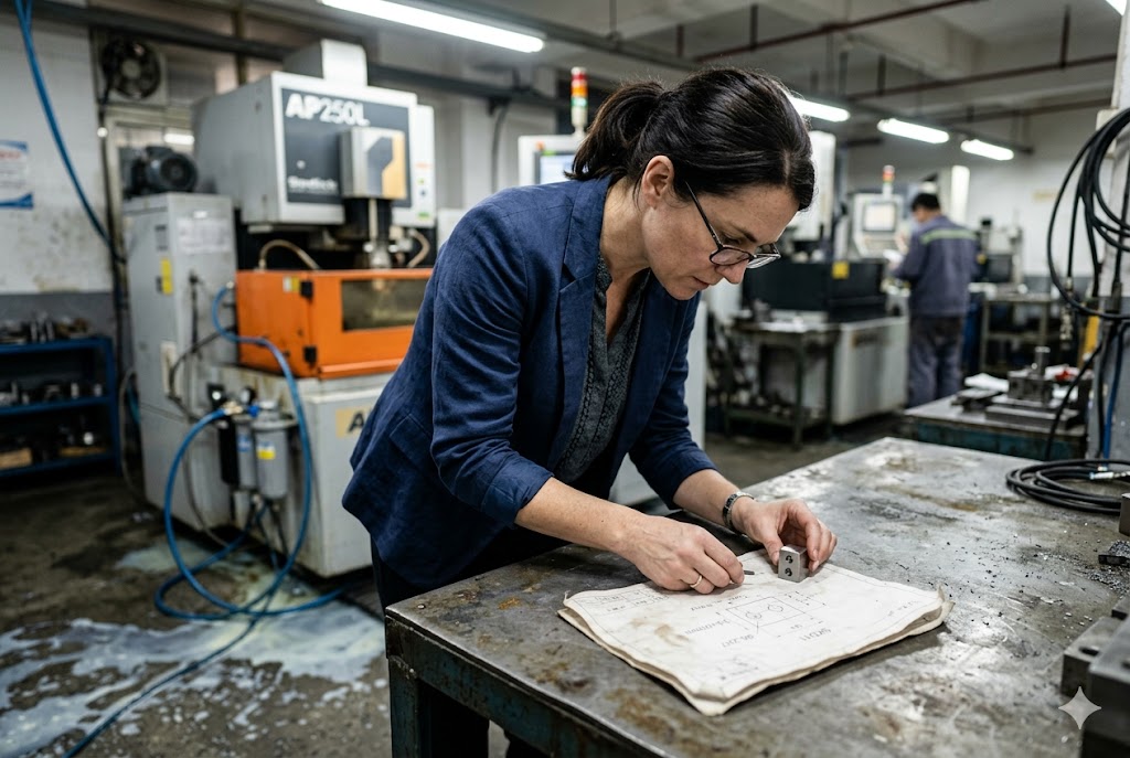
We run into this question constantly when clients send us drawings for carbide tooling components or tungsten steel dies. The assumption — that these materials might be too hard to machine cleanly — causes real delays in sourcing decisions.
Wire EDM is not just suitable for superhard materials — for tungsten carbide, hardened tool steel above 60 HRC, titanium alloys, and Inconel, it is often the only practical precision machining method. Because wire EDM uses electrical discharges rather than cutting force, hardness does not limit what the process can cut — only how fast it cuts.
This article walks through the key questions purchasing managers ask us before placing carbide EDM orders. Generator settings, wire wear, Chinese supplier experience, and achievable tolerances — we cover each one.
What Wire Type and Generator Settings Are Needed to Cut Carbide With EDM?
When our engineers first reviewed carbide EDM parameters for a US tooling client, the difference from standard steel settings was immediately clear. Wrong settings on carbide do not just slow the job — they crack the part.
For wire EDM on carbide, use a Φ0.1mm brass wire with tensile strength ≥1,200 N/mm², peak current of 3–5A, pulse-on time of 1–3μs, and pulse-off time of 10–15μs. A kerosene-based dielectric at 5–15μS/cm conductivity is strongly preferred over deionized water to protect the cobalt binder from leaching.

Why Carbide Behaves Differently From Steel
Tungsten carbide (WC-Co) is not a uniform material. It is a composite: hard tungsten carbide particles held together by a cobalt binder. The cobalt content typically runs between 6% and 15% by composition. That cobalt binder has much higher electrical conductivity than the carbide particles around it.
This matters because wire EDM erodes material through the binder first 1. Cobalt is removed faster than the surrounding tungsten carbide matrix. If the discharge energy is too high on the first (roughing) cut, the brittle carbide matrix develops micro-cracks at the surface. These cracks are not always visible. They only show up under load — sometimes after the part reaches the customer.
Recommended Parameter Strategy
The correct approach uses a two-phase parameter strategy:
Phase 1 — Roughing cut: Run at 8–10A to remove the bulk of material. Leave a finishing allowance of 0.15–0.2mm on all surfaces. Do not try to reach final dimensions on this pass.
Phase 2 — Finishing passes: Drop to 2–3A peak current with high-frequency settings. This controls the heat-affected zone, reduces crack density, and achieves ±0.002mm path accuracy.
| Parameter | Roughing Pass | Finishing Pass |
|---|---|---|
| Peak Current | 8–10A | 2–3A |
| Pulse-On Time | 6–8μs | 1–3μs |
| Pulse-Off Time | 10–15μs | 12–18μs |
| Wire Diameter | Φ0.1–0.2mm | Φ0.1mm |
| Dielectric | Kerosene-based | Kerosene-based |
| Finishing Allowance | Leave 0.15–0.2mm | Final dimension |
The Dielectric Choice Is Not Optional
Most Chinese slow-wire EDM shops default to deionized water as the dielectric fluid. For tool steel, this is fine. For carbide, it creates a serious problem called cobalt leaching.
When carbide is submerged in deionized water, the cobalt binder undergoes electrochemical corrosion — even when the machine is idle between shifts 2. Modern machines with AC power generators reduce but do not eliminate this effect. Extended soak time in water weakens the machined surface. The part may pass dimensional inspection on the CMM and still fail prematurely in service because the surface layer has lost its binder.
Kerosene or oil-based dielectric eliminates this risk. It is the correct fluid for carbide work, and any shop that cannot confirm they have this capability should not be cutting your carbide parts.
Cutting Speed Expectation
Carbide machines at approximately 2,000–3,000 mm² per hour under standard wire EDM conditions. That is roughly four times slower than mold steel. This is not a machine quality issue. It is a direct result of carbide's high melting point and low thermal conductivity. Quote lead times should reflect this. Any supplier quoting carbide EDM at steel-equivalent speed is either quoting wrong or cutting corners on quality.
Does Cutting Tungsten Carbide Wear the EDM Wire Faster, Increasing My Cost?
Our operations team tracks wire consumption across every order. When we first ran carbide jobs alongside steel jobs on the same machines, the difference in wire usage was measurable — but the reason matters more than the number.
Cutting tungsten carbide does increase wire wear compared to tool steel, primarily because carbide requires more discharge passes and finer wire diameters for finishing. However, wire cost is a secondary concern. The real cost risk is surface micro-cracking from wrong parameters, which causes part rejection — and that is far more expensive than extra wire.

What Drives Wire Wear on Carbide
Wire wear in EDM comes from two sources: thermal erosion at the discharge point, and mechanical tension on the wire during cutting. Carbide increases thermal erosion because:
- Carbide's low thermal conductivity keeps heat concentrated at the discharge point longer.
- Tungsten carbide particles released into the gap during cutting are harder than the wire itself and increase abrasion.
- Finishing passes require finer wire (Φ0.1mm) which has less thermal mass and wears faster per unit of time.
Wire Cost vs. Part Rejection Cost
It helps to put wire cost in context. Research on EDM wire cutting parameters for tungsten carbide 3 confirms that pulse-on time and peak current are the dominant variables for both surface finish and material removal rate — wire cost is a distant secondary concern:
| Cost Factor | Approximate Impact |
|---|---|
| Wire overconsumption on carbide | +15–25% on wire material cost vs. steel |
| Re-cut due to dimensional error | Full machining time × hourly rate |
| Part rejection from micro-cracking | Part cost + rework + delayed delivery |
| Cobalt leaching (deionized water) | Undetectable until in-service failure |
The wire itself is rarely the largest variable in carbide EDM cost. A Φ0.1mm brass wire spool is not expensive. The expensive failure mode is a cracked carbide insert or die that passes dimensional inspection but fails in the field.
How to Control Wire Costs Without Compromising Quality
There are legitimate ways to reduce wire consumption on carbide jobs without sacrificing quality:
Use coated wire for finishing passes. Zinc-coated brass wire reduces wire breakage during fine finishing passes by improving tensile performance at high temperatures. The premium over plain brass wire is modest.
Optimize flush pressure. Proper flushing removes debris from the gap efficiently. Poor flushing causes secondary discharges that increase wire wear without improving cut speed.
Don't skip the roughing allowance. Trying to combine roughing and finishing into fewer passes is tempting from a speed standpoint. On carbide, it increases crack risk and wire breakage. The two-phase approach is faster in total because it avoids re-cuts.
What to Ask Your Chinese Supplier
When sourcing carbide EDM from China, ask specifically:
- What wire diameter and type do you use for carbide finishing passes?
- Do you track wire breakage rate per job?
- What is your re-cut rate on carbide parts?
A shop with no clear answers to these questions is running carbide jobs on the same settings as steel. That is a quality control red flag.
Are Chinese Suppliers Experienced in Wire EDM of Cemented Carbide Tooling Components?
In our experience supporting US clients who source carbide tooling from China, supplier capability varies far more than supplier confidence. Most shops will say yes to carbide EDM. Fewer shops have the specific equipment and process control to do it correctly.
Experienced Chinese carbide EDM suppliers exist, but they are a minority of the slow-wire EDM market. The key selection criteria are AC power generator capability, oil-based dielectric availability, documented microhardness testing on carbide jobs, and measurable process controls — not just machine brand or years in business.
The Equipment Gap
The single most important factor in supplier selection for carbide EDM is whether the shop owns a machine with an AC power generator. AC generators reduce cobalt leaching compared to DC generators. Most entry-level and mid-range Chinese slow-wire machines use DC power. AC generator machines are more expensive and are found primarily in shops that have specifically invested in superhard material capability.
When we audit suppliers for carbide tooling work, we check this first. A shop running carbide on a DC generator with deionized water is not set up for this work — regardless of their machine brand or claimed experience.
Process Control Markers That Matter
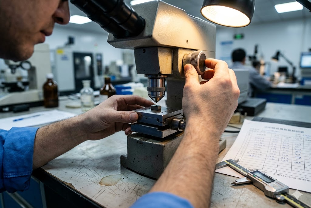
Beyond equipment, process discipline separates capable suppliers from general shops. Microhardness testing 4 of the heat-affected zone is one of the clearest indicators that a shop is actively controlling surface integrity rather than simply inspecting dimensions:
| Audit Check | What It Tells You |
|---|---|
| AC power generator confirmed | Reduces cobalt leaching risk |
| Oil/kerosene dielectric available | Eliminates cobalt leaching risk |
| Microhardness test records on file | Surface integrity is being measured |
| Tungsten ion monitoring of dielectric | Dielectric quality is actively controlled |
| Separate parameter library for carbide | They don't run carbide like steel |
| CMM + surface roughness records | Full dimensional QC, not just visual |
What "Experienced" Actually Means
A supplier who has run 500 carbide jobs on DC machines with deionized water has 500 jobs of experience doing it wrong. Experience only matters if the process was correct.
When we conduct factory audits for US clients, we ask to see process records from a comparable previous carbide job — not just the machine spec sheet. Specifically: microhardness test results confirming the heat-affected zone hardness drop does not exceed 5% of bulk hardness, surface roughness records, and CMM reports. Shops that cannot produce these records are not controlling surface integrity variables. They are inspecting dimensions and shipping.
The Cobalt Leaching Risk in Practice
Cobalt leaching is the most common hidden defect in carbide parts sourced from under-supervised Chinese shops. It happens when carbide parts sit submerged in deionized water between shifts — a routine occurrence when shop floor supervision is limited. The part looks fine. It measures correctly. It fails in service because the surface layer has lost its binder and become brittle.
Monitoring tungsten ion concentration in the dielectric fluid is a process control step that identifies when this is happening. When concentration exceeds 150ppm, the fluid should be replaced. Most general-purpose shops do not monitor this at all.
Our Recommendation
We recommend US purchasing managers request, before ordering, a sample part or process qualification run for carbide EDM jobs. Ask for microhardness test records 5 and CMM reports from the sample. If a supplier cannot or will not provide these, they are not the right partner for precision carbide tooling.
What Tolerances Are Achievable When Wire EDM Cutting Hardened Tool Steel vs. Carbide?
Our engineering team fields this comparison regularly from clients who are deciding between a carbide and a hardened steel solution for tooling components. The tolerance question is real, but the answer is more nuanced than a single number.
Wire EDM can achieve ±0.002–0.005mm on both hardened tool steel and carbide under optimized conditions. Carbide requires more finishing passes and stricter parameter control to reach equivalent surface quality. The heat-affected zone on carbide is thicker and more crack-prone than on steel at equivalent discharge energy settings.
Surface Integrity: Carbide vs. Tool Steel
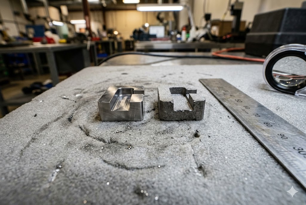
The fundamental difference between cutting carbide and hardened steel is not dimensional tolerance — it is surface integrity. Both materials can reach tight tolerances with a skilled operator. But what happens at the cut surface is different.
In tool steel, spark energy is distributed across the metal matrix relatively uniformly. The recast layer (white layer) is predictable in thickness and can be removed or minimized with trim cuts.
In carbide, the spark energy disintegrates the cobalt binder at the cut surface and releases tungsten carbide particles into the gap. Because carbide has very low thermal conductivity, the discharge heat stays concentrated at the spark point rather than spreading into the bulk material. This produces:
- A thicker recast layer than equivalent energy on steel
- Higher crack density at the surface
- A heat-affected zone that can extend deeper than on steel
These are not defects that appear on a CMM measurement 6. They are subsurface conditions that affect fatigue life, edge strength, and wear resistance.
Tolerance Comparison Table
| Condition | Hardened Tool Steel (60–65 HRC) | Carbide (WC-Co, 6–15% Co) |
|---|---|---|
| Achievable dimensional tolerance | ±0.002–0.003mm | ±0.002–0.005mm |
| Surface roughness (Ra) after finishing | 0.1–0.4μm | 0.2–0.6μm |
| Recast layer thickness | 2–5μm (optimized) | 5–15μm (optimized) |
| Number of passes for finish quality | 2–3 | 3–5 |
| Cutting speed relative to mild steel | ~60–70% | ~20–25% |
| Cobalt leaching risk | None | High (water dielectric) |
Special Cases: Titanium and Inconel
Two materials that come up frequently in aerospace and medical tooling are titanium and Inconel.
Titanium 7 has thermal conductivity nearly six times lower than steel. Heat generated during EDM stays in the cutting zone. This makes titanium prone to microcracking and heat-damaged surface layers if spark parameters are not precisely controlled. Titanium requires slower cutting speeds, higher flushing pressure, and carefully controlled pulse energy. These are not optional adjustments for aerospace or medical parts.
Inconel 718 8 and other nickel superalloys accumulate thermal damage during the roughing cut — residual stress, microcracks, porosity, and grain growth. This damage can be largely removed by subsequent trim cuts at reduced discharge energy. Decreasing pulse-on time combined with high servo voltage inhibits microcrack formation and improves cracking resistance compared to high pulse-on time settings.
What Quality Assurance Should Include
For carbide and superhard material EDM, dimensional reports alone are insufficient. A proper quality package for precision carbide parts 9 should include:
- CMM dimensional verification against drawing tolerances
- Surface roughness (Ra) measurement at specified locations
- Microhardness testing to confirm heat-affected zone hardness drop ≤5% of bulk hardness
- Dielectric fluid tungsten ion concentration records
- Thermal imaging records confirming cutting zone temperature ≤80°C during production
Cutting zone temperature control is a detail that separates precision shops from general shops. Maintaining ≤80°C in the cutting zone prevents heat-affected zone expansion during long production runs. Most shops do not monitor this at all. Research on titanium alloy recast layer formation during wire EDM 10 confirms that low thermal conductivity in superhard materials makes cutting zone thermal management especially critical for aerospace and medical components.
Conclusion
Wire EDM is the right process for carbide and superhard materials — but only when the supplier has the correct equipment, parameters, and quality controls. Dimensional tolerance is achievable. Surface integrity is the harder problem to manage, and it requires more than a CMM report to verify.
Footnotes
1. Overview of how wire EDM cuts tungsten carbide, including binder erosion and key process precautions. ↩︎
2. Comprehensive guide to tungsten carbide wire EDM parameters, dielectric fluid selection, and quality monitoring. ↩︎
3. Peer-reviewed study on optimizing EDM wire cutting parameters for tungsten carbide surface quality. ↩︎
4. Explanation of microhardness testing methods for measuring heat-affected zone depth in machined metals. ↩︎
5. Guide to microhardness vs. macrohardness testing and their roles in surface integrity verification. ↩︎
6. Introduction to CMM inspection capabilities, limitations, and its role in dimensional quality control. ↩︎
7. Challenges of wire EDM on titanium alloys, including thermal concentration and microcracking risks. ↩︎
8. Springer study on Inconel 718 surface integrity across different wire EDM energy modes and trim cuts. ↩︎
9. Comprehensive CMM inspection guide covering measurement principles and quality reporting for machined parts. ↩︎
10. Springer research on recast layer formation in titanium wire EDM and the role of thermal conductivity. ↩︎



