Skip to main content Skip to footer
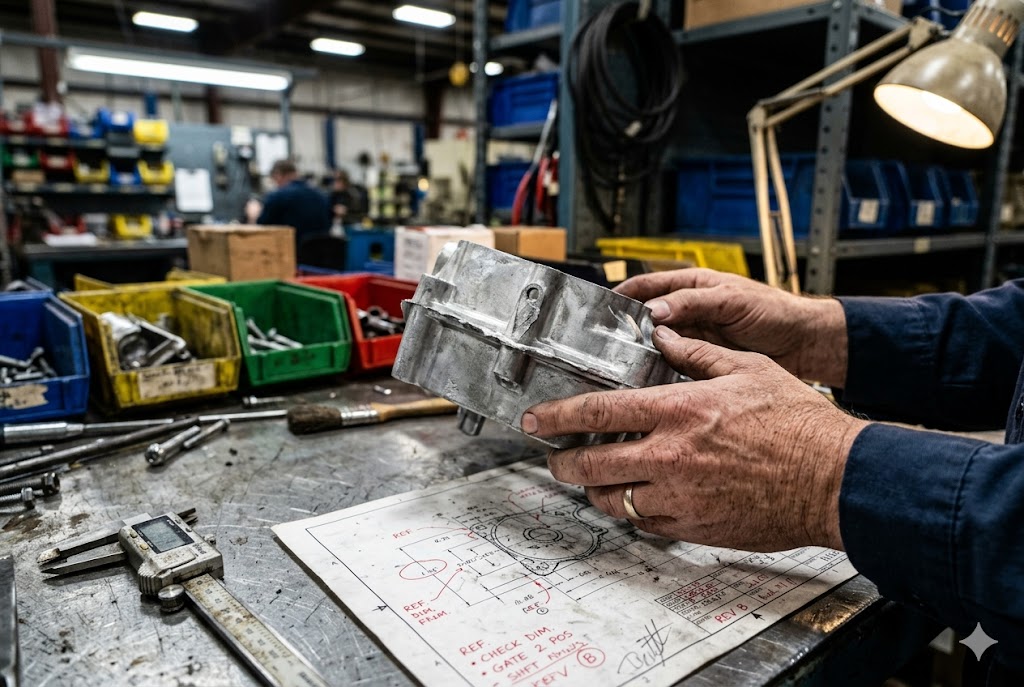
Every year, our team reviews hundreds of part drawings before a single gram of aluminum enters a die cavity. We see the same costly mistakes — undercuts left in, walls too thin, zero draft on deep pockets. By the time a buyer realizes the tool is wrong, they've already paid for steel.
A proper DFM review before tooling starts covers parting line placement, draft angles, wall thickness, fillet radii, undercuts, gate location, shrinkage compensation, tolerance classification, ejector pin layout, and secondary operation requirements. Done right, it prevents most defects before a single tool cut is made. Expect a written, annotated report — not verbal assurances.
Most suppliers will say "no problem" to your drawing without reading it carefully. This article tells you exactly what to ask for — and why each item matters.
Should I Expect Design Changes Related to Draft, Wall Thickness, and Machining Allowance?
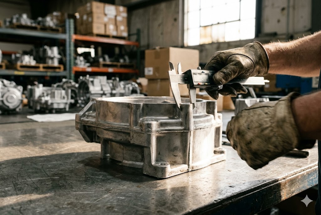
When we run a wall thickness analysis 1 on an incoming CAD file, we flag problem areas before we ever discuss price. Buyers who skip this step discover the issues at T1 sample inspection, after the tool has already been cut and hardened.
Yes — expect your supplier to recommend changes to draft angles, wall thickness, and machining allowance on almost every new part. These changes are not criticism of your design. They reflect the physical realities of molten metal flowing into a steel cavity and solidifying under pressure. Accepting them early saves money.

Why Draft Angles Cannot Be Ignored
Draft angles 2 are the slight taper applied to vertical walls so the casting can be ejected cleanly. Without enough draft, the part grips the steel. The ejector pins push harder. Over thousands of shots, the tool surface and the part surface both suffer.
For aluminum die casting, outer surfaces typically need at least 2° of draft. Inner surfaces (cores and pockets) need at least 1°. Deeper features and textured surfaces need more — sometimes 3° to 5°.
Here is a quick reference for minimum draft angles:
| Surface Type | Minimum Draft (Aluminum) | Minimum Draft (Zinc) |
|---|---|---|
| Outer flat wall | 2° | 1° |
| Inner pocket or core | 1° | 0.5° |
| Textured cosmetic surface | 3°–5° | 2°–3° |
| Deep rib (>20mm depth) | 3° | 1.5° |
Your DFM report should call out every surface below these minimums by name and location — not a general note that "some areas need more draft."
Wall Thickness: Too Thin and Too Thick Are Both Problems
Walls below 1.5mm for aluminum risk incomplete fill, cold shuts, and porosity. Walls above 6mm create isolated thick sections that cool slowly, shrink unevenly, and trap gas.
Abrupt thickness changes — a 1mm wall meeting a 5mm boss, for example — cause shrinkage stress and visible sink marks. The supplier should recommend blending tapers or adding cored pockets to reduce mass.
| Wall Thickness Issue | Likely Defect | Recommended Fix |
|---|---|---|
| Below 1.5mm | Cold shut, incomplete fill | Increase wall or adjust gate |
| Above 6mm (isolated) | Shrinkage porosity | Core out the section |
| Abrupt transition >2:1 ratio | Sink marks, stress crack | Add blending radius or taper |
| Thin wall feeding a thick boss | Boss porosity | Add radial ribs, reduce boss diameter |
Machining Allowance: What Gets Left On and Why
When a face must be machined after casting, the supplier adds extra material — the machining allowance — so the machined surface ends up at the correct final dimension. Typical allowance is 0.3mm to 1.0mm per face.
If a buyer's drawing shows a final machined dimension with no allowance called out, the supplier must assume and add it. If they assume wrong — or don't add it at all — the machined part is undersized and scrap.
Your DFM report should list every face that requires post-cast machining and state the allowance added. You review and approve it before tooling starts.
How Can DFM Feedback Help Me Reduce Defects Before I Commit to Tooling?
Our engineers have found that the majority of recurring production defects — shrinkage porosity 3, cold shuts, dimensional drift, and surface cracks — trace back to geometry decisions that were locked in at the tooling stage. Changing them after the fact means EDM rework, re-hardening, and re-sampling.
DFM feedback reduces defects by resolving root causes before steel is cut. Parting line placement controls flash. Fillet radii prevent tool cracking and metal flow turbulence. Gate location determines where porosity accumulates. Ejector pin placement prevents witness marks on critical surfaces. Every DFM action is a defect removed from your future production runs.

Parting Line Placement: Small Decision, Big Consequences
The parting line 4 is where the two halves of the die meet. Where it lands on your part determines where flash forms, where mismatch steps appear, and how easy the part is to trim and inspect.
A good supplier proposes the parting line location before any design is finalized. They show you exactly where it will be on a 3D screenshot or annotated drawing, explain the tradeoffs, and document the cosmetic implications.
A poor supplier places the parting line where it is easiest for them — which may be across a sealing face, a cosmetic class-A surface, or a machined datum.
Fillet Radii: Protecting the Tool and the Part
Fillet radii 5 at sharp internal corners in the die cavity address two critical problems. First, they reduce stress concentration points in the tool steel. Thermal cycling — heating to 700°C and cooling each shot — initiates fatigue cracks at sharp corners first. A cracked cavity surface prints a raised line on every part.
Second, sharp corners in the flow path create turbulence in the liquid metal. Turbulence folds oxide films and entraps air, producing porosity at those locations in the part.
The DFM report should state a minimum internal fillet radius for every sharp corner:
| Alloy | Minimum Internal Fillet | Preferred Fillet |
|---|---|---|
| Aluminum (A380) | 1.0mm | 1.5mm–2.0mm |
| Zinc (Zamak 3/5) | 0.5mm | 1.0mm–1.5mm |
| Magnesium (AZ91D) | 1.0mm | 2.0mm |
Generic instructions to "add fillets where needed" are not acceptable. Each corner should be called out specifically with a required radius value.
Gate Location: Where Quality Is Born
Liquid metal enters the cavity at the gate location 6. The metal closest to the gate fills first and is densest, with the least porosity. The metal farthest from the gate — the last-fill zone — is coolest, slowest, and most likely to entrap gas.
If your part has a structural bolt boss, a sealing groove, or a pressure-critical wall at the last-fill location, you have a quality problem baked into the tool design. The solution is to move the gate or use vacuum-assisted casting — but you must know about this before the tool is built, not after T1 samples fail a leak test.
Your supplier's DFM report should show a gate location diagram with the expected fill sequence and identify which features sit in the last-fill zone.
Ejector Pin Witness Marks: Approve Them Early
The ejector pin layout 7 determines where each pin pushes the casting out of the die. Each pin leaves a small witness mark — a raised or recessed circle — on the part surface. Suppliers default to placing pins where they are mechanically convenient. This convenience may conflict with your requirements.
Witness marks on sealing faces prevent leak-tight assembly. Marks on datum surfaces misalign machining fixtures. Marks on cosmetic class-A surfaces are rejected by end customers.
Review and approve the ejector pin layout from the DFM report. Relocating pins after the tool is built requires EDM cavity repair and rehardening — expensive and slow.
What DFM Recommendations Can Save Me Money Without Hurting Performance?
When we help clients compare supplier quotations, we consistently find that the parts with the lowest piece prices are not the ones with the cheapest hourly rates — they are the ones where smart design for manufacturability 8 decisions reduced undercuts, simplified parting geometry, and eliminated unnecessary secondary operations.
The highest-value DFM cost savings come from eliminating unnecessary undercuts, replacing solid thick sections with cored geometry, simplifying parting line complexity, and reducing secondary machining scope. Each of these changes lowers tooling cost, cycle time, and scrap rate simultaneously — without changing part function.

Eliminating Undercuts: The Biggest Single Saving
An undercut is any feature that cannot be released in the main parting direction. Releasing it requires a mechanical slide, a lifter, or a collapsing core — all of which add $3,000 to $8,000 or more per mechanism to the tool price, increase maintenance frequency, and are a common source of production downtime.
Many undercuts in imported part designs are inherited from machined predecessors or injection-molded designs. They were never needed for die casting. A competent supplier identifies which undercuts are eliminable through minor geometry changes — a slot converted to an open groove, a blind hole converted to a through hole accessible from the parting surface.
The DFM report should classify every undercut:
- Can be redesigned away (preferred)
- Requires a slide (add cost — justify functionally)
- Requires a lifter (moderate cost)
- Requires a collapsing core (highest cost and risk)
Coring Out Thick Sections
Solid bosses and pads above 6mm thick create shrinkage porosity and extend cycle time. Coring — adding a pocket into the thick section from the back side — reduces mass, accelerates cooling, and eliminates the porosity hotspot.
The cored pocket adds a small core pin to the tool, which is far cheaper than managing a porosity-prone thick section through process adjustments. Reduced cycle time also lowers piece price on every unit produced.
Reducing Secondary Machining Scope
Every post-casting operation — milling a face, drilling and tapping holes, reaming a bore — adds cost per piece. DFM can reduce this scope in two ways.
First, features that appear to require machining may be achievable as-cast with tighter process control — saving the machining cost entirely. Second, features that must be machined can be repositioned or reoriented to use standard tooling, shorter reach, and simpler fixturing — reducing machining cycle time.
Your DFM report should explicitly classify every toleranced feature:
| Feature Category | As-Cast Achievable? | Notes |
|---|---|---|
| General dimensions ±0.3mm | Yes | Standard process capability |
| Hole position ±0.15mm | Sometimes | Depends on location relative to parting line |
| Bore diameter H7 tolerance | No | Requires reaming after casting |
| Flat face Ra 1.6μm | No | Requires milling; include machining stock |
| Thread M6 or larger | No | Drill and tap after casting |
How Do I Know Whether My Supplier's DFM Review Is Detailed Enough?
In our experience working with dozens of factories across China and Vietnam, there is a wide gap between a genuine DFM review and a one-page checklist signed off without opening the 3D file. Knowing the difference protects your tooling investment.
A sufficient DFM review produces a written, annotated report that addresses every toleranced feature, identifies specific surfaces by location and name, includes 3D screenshots with callouts, proposes explicit remediation for each issue, and classifies tolerances as as-cast or requiring post-cast machining. A verbal "no problem" or a generic one-page checklist is not a DFM review.

The Minimum Content a Real DFM Report Must Include
Use this checklist when evaluating what your supplier sends you:
- Parting line location shown on a 3D screenshot with cosmetic and dimensional implications documented
- Draft angle analysis with every non-conforming surface identified by location and measured angle
- Wall thickness analysis showing minimum and maximum values, flagging all violations
- Fillet radius recommendations with specific values per location, not a blanket instruction
- Undercut classification with resolution strategy and tooling cost impact for each
- Gate and overflow layout with fill sequence and last-fill zone identified
- Shrinkage factor stated explicitly, with high-risk dimensions flagged
- Tolerance classification table — as-cast vs. machined for every toleranced feature
- Ejector pin layout with witness mark locations shown on 2D drawing
- Secondary operation list with flagged design issues affecting machinability
Red Flags That Indicate an Inadequate Review
A supplier is not taking DFM seriously if they:
- Return your drawing with only a price and lead time, no written comments
- Send a generic checklist not specific to your part geometry
- Say "we've made similar parts before" without annotating your file
- Provide no 3D screenshots or annotated drawings
- Do not classify tolerances as achievable as-cast or requiring machining
How to Use DFM Findings as a Supplier Evaluation Tool
A detailed DFM report is not just a design aid — it is a signal of the supplier's engineering capability. A supplier who can produce a thorough, annotated, part-specific DFM document has the engineering team, the CAD tools, and the process knowledge to back up their price and lead time commitments.
We routinely use the quality of a supplier's DFM report as one of the evaluation criteria when auditing factories on behalf of our clients. A factory that cannot produce a real DFM review before tooling is a factory that will struggle to produce a real PPAP 9 or FMEA 10 during production.
If your supplier is unable or unwilling to provide the items above, treat it as a serious qualification concern — not a minor administrative gap.
Conclusion
Before you commit to tooling, demand a written DFM report that covers all ten areas above. It costs your supplier time — which is exactly why a willingness to provide it signals a trustworthy partner.
Footnotes
1. Dynacast's beginner guide explains why uniform wall thickness is the most critical rule in die cast design. ↩︎
2. Xometry Pro outlines how draft angles directly affect tool life, surface quality, and overall part cost in die casting. ↩︎
3. Sunrise Metal details the causes, appearance, and remedies for shrinkage porosity in aluminum die castings. ↩︎
4. CASTMOLD's structural design guide covers 14 DFM principles including parting line selection for die cast parts. ↩︎
5. EMP Tech's guide explains how fillet radii prevent tool fatigue cracks and reduce metal flow turbulence in die casting. ↩︎
6. Yongzhu Casting's aluminum design guide shows how gate placement controls fill sequence and porosity location. ↩︎
7. Premium Parts' die casting design guidelines cover ejector pin placement and its impact on part surface quality. ↩︎
8. Xometry's DFM resource explains how design for manufacturability reduces production costs and defect rates. ↩︎
9. Quality-One's PPAP resource details the 18 elements of the Production Part Approval Process and its five submission levels. ↩︎
10. ASQ's FMEA resource defines failure mode and effects analysis and when to apply it in manufacturing quality planning. ↩︎