 Skip to main content Skip to footer
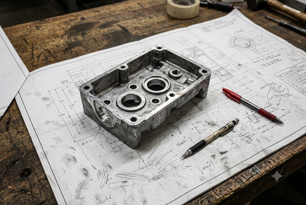
Every week, clients send us drawings and ask the same thing: "Is this a die casting job?" It sounds simple. But the answer depends on geometry, volume, material, and what the part needs to do after casting. Get it wrong and you pay for tooling you can't use — or worse, parts that fail inspection.
Die casting is suitable for metal parts with complex shapes, thin walls, and high production volumes — typically aluminum, zinc, or magnesium alloys. The process is cost-effective when unit quantities exceed several thousand pieces. Parts must have wall thicknesses between 1mm and 5mm and draft angles of 1–3° to fill and release cleanly.
If you are unsure whether die casting fits your design, read on. We break it down by geometry, material, volume, cost, and supplier capability — so you can make the right call before you commit to tooling.
How Do I Know Whether My Part Geometry Fits the Die Casting Process?
When our engineers review a new drawing, the first thing they check is geometry — not price, not volume. Geometry determines whether the part can actually be cast. A wrong call here means scrapped tooling and wasted time.
A part fits die casting geometry when it has walls between 1mm and 5mm thick, uniform cross-sections, draft angles of at least 1°, and no deep undercuts that block mold opening. Complex external features like ribs, bosses, and fins are fine. Deep internal cavities that require slides or cores add cost and risk.
Wall Thickness: The First Test
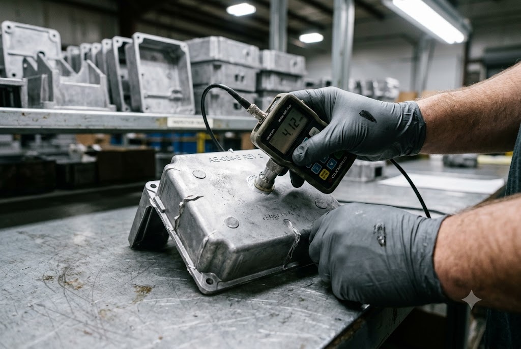
Wall thickness is the single most important geometry check. High-pressure die casting (HPDC) 1 forces molten metal into a steel mold at high speed. Thin walls fill fast. Thick walls trap heat and create porosity.
The safe range is 1mm to 5mm. Below 0.8mm, the metal may not fill completely. Above 6mm, you get shrinkage voids inside the wall. Those voids are invisible from the outside but they weaken the part and cause leaks in pressure applications.
| Wall Thickness | Result | Risk |
|---|---|---|
| Below 0.8mm | Incomplete fill | Short shots, scrap |
| 1mm – 5mm | Optimal fill and solidification | Low porosity, good strength |
| Above 6mm | Slow solidification | Internal porosity, dimensional variation |
If your part has sections that vary widely in thickness — say, a 1.5mm outer wall connecting to a 7mm boss — that junction will be a problem. A good supplier will flag this in DFM review and suggest coring out the thick section.
Draft Angles: The Second Test
Every vertical face on a die cast part needs a draft angle 2. This is the slight taper that allows the part to release from the mold without dragging. No draft means the part locks in the mold.
The standard is 1° to 3° on external faces. Internal walls that form pockets or holes often need 2° to 5°. If your drawing shows 0° on a vertical wall, the tool maker will either add draft and adjust your dimensions, or ask you to revise the drawing. Neither is free.
Undercuts and Side Actions
Undercuts are features that prevent the mold from opening in a straight line. A through-hole running sideways across a part is a classic undercut. So is a snap-fit groove on an internal wall.
Undercuts are solvable. The mold can include side actions — moving steel inserts that retract before the mold opens. But each side action adds tooling cost and one more mechanical point that can wear or misalign. If your design has undercuts that are not functionally necessary, it is worth redesigning before you pay for the tool.
Feature Consolidation: A Real Advantage
One thing die casting does well is consolidate features. A part that would otherwise be machined from a block of aluminum — with separate bosses bolted on, fins welded in, and threads tapped manually — can often be cast as a single piece. Bosses, ribs, heat-sink fins, and mounting pads can all come out of the mold in one shot.
This reduces downstream labor. It also reduces assembly error. Fewer joints mean fewer failure points.
| Feature Type | Die Casting Compatible? | Notes |
|---|---|---|
| External ribs and fins | Yes | Add stiffness without added weight |
| Threaded bosses | Yes | Cast boss, tap thread post-cast |
| Bearing bores | Partial | Cast near-net, then CNC bore to tolerance |
| Internal channels | Limited | Possible with cores; adds cost |
| Snap fits and barbs | Careful | May need side actions |
Should I Choose Die Casting for High-Volume Metal Parts with Complex Shapes?
We see this question most often from purchasing managers who are comparing die casting against CNC machining for a new part launch. The honest answer is: it depends on your volume. Die casting has a high entry cost and a low per-part cost. That curve only works in your favor above a certain quantity.
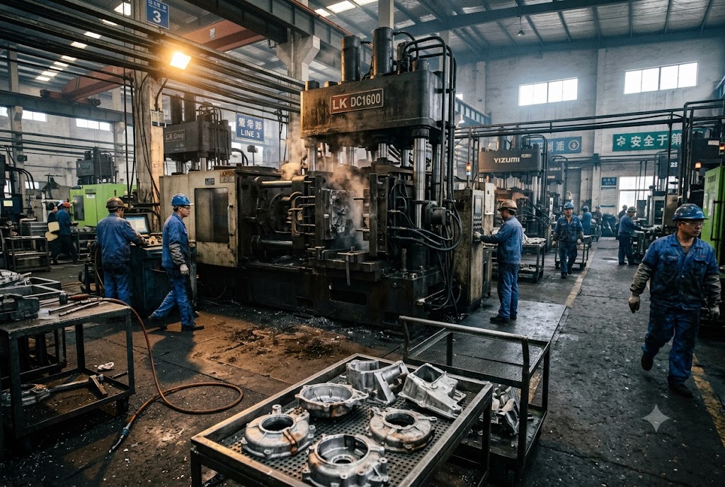
Die casting becomes the right choice for high-volume metal parts with complex shapes when your production run exceeds several thousand units. At that scale, the per-part cost drops well below CNC machining. Complex geometry that would take hours to machine is produced in seconds per cycle with a die cast tool.
The Volume Breakeven Point
Tooling for a die cast mold typically costs between USD 8,000 and USD 50,000 depending on complexity, number of cavities, and material. A simple single-cavity aluminum die casting tool might cost USD 10,000. A multi-cavity tool for a small zinc component could run USD 20,000–30,000.
That cost is fixed. You pay it once. After that, each part costs a fraction of what CNC machining would cost for the same geometry.
| Production Volume | Recommended Process | Reason |
|---|---|---|
| Under 500 units | CNC machining | No tooling cost; flexible |
| 500–3,000 units | Evaluate both | Depends on geometry and tolerance |
| 3,000–10,000 units | Die casting likely better | Tooling cost spread across volume |
| Above 10,000 units | Die casting strongly preferred | Per-part cost advantage is significant |
Cycle Time and Output Rate
A die casting machine runs one shot every 15 to 60 seconds depending on part size. A multi-cavity tool doubles or quadruples that output per cycle. CNC machining on the same part could take 5 to 30 minutes per unit. For a part at 50,000 units per year, the production time difference is enormous.
Complex Shapes: Where Die Casting Wins Clearly
CNC machining struggles with internal features. You need to reach every surface with a cutting tool. That limits what geometry you can achieve without multi-setup fixturing or EDM. Die casting has no such constraint. The mold cavity defines the part. Internal bosses, draft-angled pockets, and integrated fins all come out of the die with no extra machining.
The tradeoff is tolerance. Die casting holds ±0.1mm to ±0.3mm on most features. CNC machining holds ±0.01mm or tighter. If your part has a few critical dimensions — a bearing bore, a sealing face — those are machined after casting. The rest of the part comes off the die at net shape, no further work needed.
What This Means for Your Cost Model
When you import from China, tooling cost is your main upfront risk. If the tool is built correctly and the part runs well, you amortize that cost quickly. At 10,000 units, a USD 15,000 tool adds USD 1.50 per part. At 50,000 units, it adds USD 0.30. That is manageable.
The risk is rework. A tool that was built without proper DFM review may need modifications. Each modification costs money and delays your first shipment. This is why supplier selection and upfront engineering review matter more than the quoted tooling price alone. Understanding die casting design principles for manufacturability 3 early in the process can substantially reduce these downstream costs.
What Product Features Make Die Casting a Cost-Effective Option for Me?
Cost-effectiveness in die casting is not just about volume. It also comes from the part itself — its material, its surface requirements, and how many secondary operations it needs. Some parts are naturally cheap to die cast. Others carry hidden costs that only show up after the tool is built.
Die casting is most cost-effective when a part uses aluminum, zinc, or magnesium alloy; requires a smooth as-cast surface; consolidates multiple features into one component; and runs at volumes above several thousand units. These factors together lower per-part cost and reduce downstream finishing and assembly labor.
Material Choice and Its Impact on Cost
The alloy you choose affects tool life, cycle time, surface finish, and downstream options. Aluminum is the most common choice for Chinese die casting exports. It is light, strong, and accepts a wide range of surface treatments. Common casting grades such as ADC12 and A380 4 offer a proven combination of fluidity, strength, and dimensional stability across automotive, industrial, and electronics applications.
Zinc die casting using Zamak alloys 5 runs at lower temperatures than aluminum. Tools last longer. Cycle times are shorter. The alloy fills very thin walls — down to 0.5mm — and produces extremely smooth surfaces straight from the die. Zinc parts are typically heavier than aluminum at the same volume, but for small, precise components, zinc often wins on total cost.
Magnesium die casting with AZ91D 6 uses the lightest structural metal available. It is used when weight is the primary constraint. VR headset frames, laptop structures, and handheld device housings are typical applications. Magnesium die casting requires controlled handling and fire safety measures in the foundry, which adds process cost.
| Alloy | Typical Wall Min. | Surface Quality | Best Application |
|---|---|---|---|
| Aluminum (ADC12, A380) | 1.0mm | Good | Automotive, industrial, electronics enclosures |
| Zinc (Zamak 3, Zamak 5) | 0.5mm | Excellent | Small precision parts, consumer hardware |
| Magnesium (AZ91D) | 0.8mm | Good | Lightweight structures, handheld devices |
Surface Finish as a Cost Driver
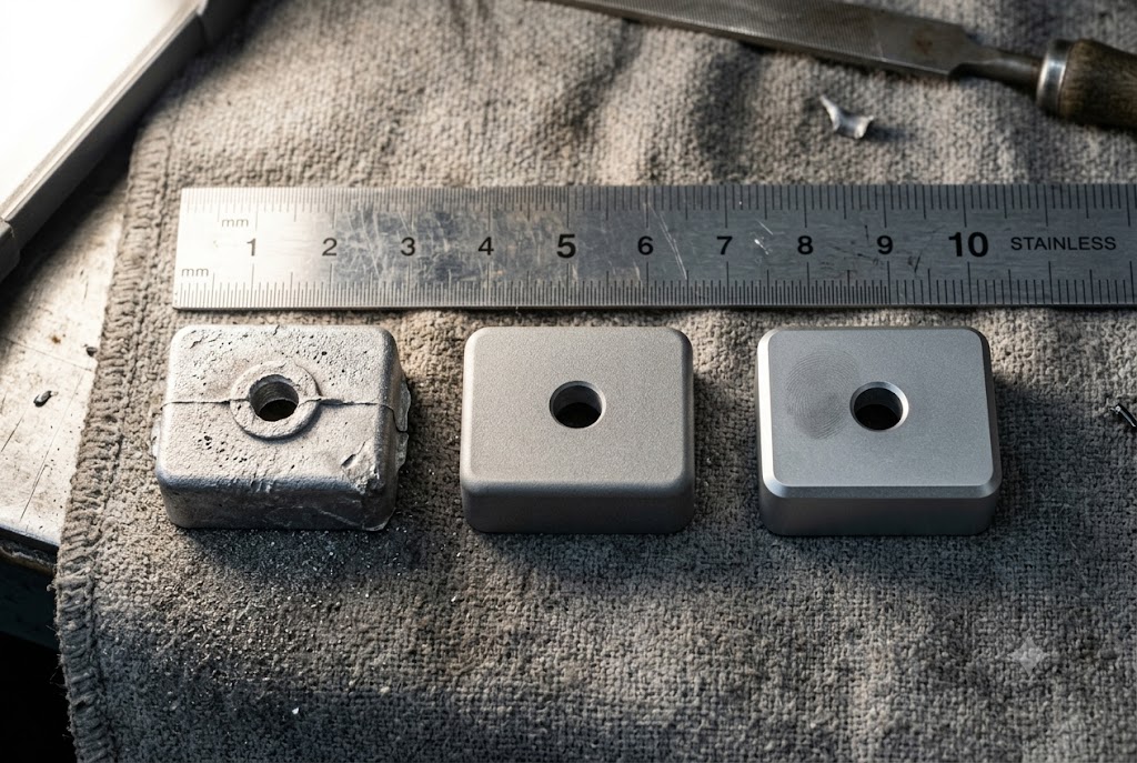
Die casting produces smoother surfaces than sand casting or investment casting in most cases. That matters because finishing operations cost money. If your part can go from the die to anodizing or powder coating without intermediate grinding, you save labor at every step.
Aluminum die castings accept anodizing, chromate conversion, powder coating, and e-coat 7. Zinc accepts chrome plating and powder coating well. The as-cast Ra surface roughness on a well-maintained die is typically 1.6 to 3.2 μm — acceptable for most cosmetic and functional applications without polishing.
Feature Consolidation Reduces Assembly Cost
This point is easy to overlook when comparing quotes. A die cast part that combines what used to be three machined components into one casting eliminates two assembly operations, two sets of fasteners, and two opportunities for assembly error. That saving does not show up on the die casting quote. It shows up in your total landed cost.
When reviewing a new project, our team always asks: "Is this part currently assembled from multiple pieces?" If yes, we check whether a single casting can consolidate them. Sometimes it can. When it does, the tooling investment pays back faster than the volume breakeven calculation alone would suggest.
Can My Supplier Help Me Decide Whether Die Casting Is Right for My Design?
This is the question purchasing managers ask last — but it should be asked first. A capable supplier does more than quote a price. They review your drawing for manufacturability before you commit to tooling. That review can save you tens of thousands of dollars.
A qualified die casting supplier should provide DFM (Design for Manufacturability) feedback on wall thickness, draft angles, parting line placement, and gate location before quoting the tool. If a supplier skips DFM review and goes straight to price, that is a red flag — it means they will build what you sent, not what will actually work.
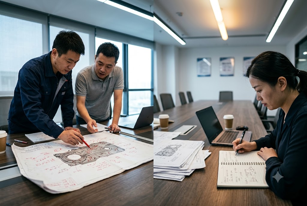
What Good DFM Review Looks Like
When we receive a drawing for a potential die casting project, our engineering team runs through a standard checklist before any quote is prepared. This is not optional — it protects both sides.
A proper DFM review for die casting 8 covers:
- Draft angles: Are all vertical faces tapered enough to release from the die?
- Wall thickness: Are there sections outside the 1–5mm range that need redesign?
- Parting line: Where will the mold split? Does that line create a visible seam on a cosmetic surface?
- Gate location: Where will molten metal enter the mold? Does that location avoid critical surfaces?
- Ejector pin placement: Where will the pins push the part out? Will those marks be visible or functional?
- Secondary operations: Which surfaces need post-cast CNC machining? Is there enough stock to hold the required tolerance?
A supplier who sends back DFM comments within 48 hours of receiving your drawing is a supplier who has done this before. A supplier who sends a price the next day with no questions has probably not looked at the drawing closely. The die casting design guidelines published by NADCA 9 provide a useful independent benchmark for evaluating whether a supplier's feedback meets industry standards.
Pressure-Critical and Weld-Critical Applications
Some applications require more than standard HPDC. Hydraulic valve bodies, pump housings, and fluid connectors must pass pressure tests. Standard die casting produces micro-porosity — tiny voids inside the metal. Most parts never leak. But in pressure applications, those voids become a liability.
The solutions are vacuum-assisted die casting 10 and T5 or T6 heat treatment. Vacuum die casting pulls air from the mold cavity before injection, reducing trapped gas and porosity. T6 heat treatment improves mechanical properties and can close surface porosity for weld-critical applications. Both options must be specified upfront. They are not standard. They cost more. And not every foundry in China offers them.
If you need a pressure-tight casting, tell your supplier before the tool is built. If they do not ask about this and your part will see hydraulic pressure, ask them directly: "Can your process meet a pressure test at X bar?" If they hesitate, find a different foundry.
The Role of a Sourcing Partner
For purchasing managers who source from multiple suppliers across China and Vietnam, evaluating each foundry's die casting capability individually is time-consuming. Our team does this work on your behalf. We visit the foundry, review their equipment, check their in-process quality records, and assess whether their DFM process is real or just a formality.
We have walked away from foundries that quote well but cannot show us their SPC data or their tool maintenance logs. Those foundries produce scrap at scale. That scrap becomes your problem on arrival.
Importing custom die castings from China is manageable when you have the right supplier and the right process controls in place. It becomes expensive when you find out the tool was built wrong after it has already been cut.
Conclusion
Die casting suits complex, high-volume metal parts in aluminum, zinc, or magnesium. Geometry, wall thickness, and volume determine fit. A qualified supplier reviews your design before the tool is cut — that step protects your investment and prevents costly rework after production begins.
Footnotes
1. Overview of the HPDC process: injection mechanics, materials, cycle times, and precision capabilities. ↩︎
2. Practical guide to draft angles in die casting: how much taper to apply and where, by feature type. ↩︎
3. Beginner's guide to designing for die cast manufacturability, covering tolerances and DFM trade-offs. ↩︎
4. Buyer's guide to HPDC aluminum alloys including ADC12 and A380: process parameters and supplier selection. ↩︎
5. Comprehensive comparison of Zamak zinc alloy grades and why they outperform other alloys for thin-wall precision parts. ↩︎
6. Properties, composition, and industrial applications of AZ91D magnesium die casting alloy. ↩︎
7. Seven surface finish options for aluminum die castings including anodizing, powder coating, and e-coat. ↩︎
8. Step-by-step guide to running an effective DFM review with suppliers before tooling is committed. ↩︎
9. NADCA-based die casting design tips covering wall thickness, draft angles, and tooling trade-offs. ↩︎
10. ScienceDirect academic overview of vacuum die casting: porosity reduction, heat treatability, and weldability. ↩︎



