 Skip to main content Skip to footer
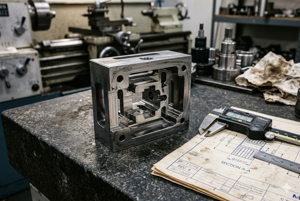
Every week, we review drawings where the buyer has already decided on a process — and wire EDM is often either overlooked or misapplied. Getting this decision right saves time and money.
Wire EDM is best suited for through-contour cuts in hard materials, tight internal corners, thin walls, punch and die sets, and complex 2D profiles that conventional milling cannot hold to tolerance. The process works by eroding material with a tensioned wire, so any geometry the wire can pass through completely — from top to bottom — is a strong candidate.
Understanding which shapes belong on a wire EDM machine — and which do not — is the clearest way to avoid rework, cost overruns, and missed delivery windows.
Can Wire EDM Cut Internal Sharp Corners or Complex Contours My Milling Can't Achieve?
When we review customer drawings, internal corners are the single most common reason a part gets routed to wire EDM. An end mill always leaves a radius equal to its own diameter at every inside corner — there is no way around it.
Wire EDM can cut internal corner radii as small as 0.06mm using a 0.1mm wire, which no rotating cutter can match. For complex 2D contours — spline profiles, gear teeth, intricate cutouts — wire EDM holds these shapes in hardened material at tolerances that milling cannot reach without a separate grinding step.
Why Rotating Tools Cannot Solve the Corner Problem
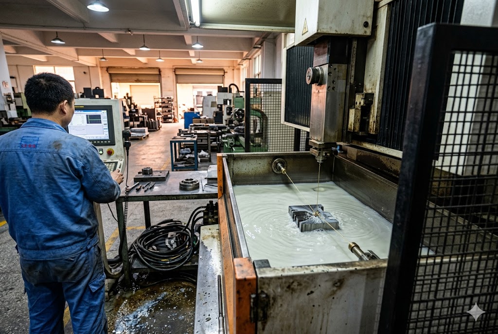
Every milling cutter is round. At any inside corner, the tool leaves a fillet equal to its own radius. A 6mm end mill leaves a 3mm corner radius. A 1mm end mill leaves a 0.5mm radius — and at that size, tool breakage becomes a real risk, especially in hardened steel.
Wire EDM removes this constraint entirely. The wire — typically 0.1mm to 0.3mm in diameter — follows the programmed path and changes direction at the corner point. The result is a corner radius determined by the wire diameter, not a tool diameter. With a 0.1mm wire, internal radii of 0.06mm are achievable under good flushing conditions. As Xact Wire EDM explains 1, because the wire electrode can be as thin as 0.1mm, wire EDM can create extremely tight internal corner radii that are simply unachievable with an end mill.
Practical Corner Tolerance — What Drawings Should Specify
There is one important nuance. At the moment the wire changes direction, slight wire flex causes the actual corner to open up by 0.001mm to 0.002mm. This is small but measurable on a CMM. For drawings where corner geometry is dimensioned and toleranced, specifying a minimum internal radius of 0.1mm is the practical design rule.
| Corner Requirement | Recommended Wire Diameter | Achievable Min. Radius | Notes |
|---|---|---|---|
| General profile | 0.25mm | ~0.15mm | Standard production wire |
| Tight features | 0.15mm | ~0.10mm | Slower cutting speed |
| Precision sharp corners | 0.10mm | ~0.06mm | Requires skilled flushing setup |
| Drawn as truly sharp | Any | Not achievable | Specify min. radius on drawing |
Complex Contours: Splines, Involute Gears, and Freeform Profiles
Any 2D profile that can be defined in a DXF or CAD file can be cut by wire EDM. Involute gear profiles, spline curves, and irregular cutout shapes all translate directly into wire paths. The machine follows the geometry without needing dedicated form cutters.
For hardened tool steel — D2, H13, M2 — this is where wire EDM has no real competition. Milling hardened steel above 58 HRC requires carbide tooling, slow feeds, and multiple passes. Wire EDM cuts at the same speed regardless of hardness. The part is hardened first, then cut to final dimension. No distortion from the heat treatment cycle affects the final profile. Research on wire EDM precision limits 2 confirms that because there is no direct tool contact, cutting forces are negligible — making it possible to machine thin walls and hardened materials without distortion from mechanical load.
For engineering teams designing punches, forming tools, or precision fixtures, this means the part in the drawing is the part you get — in the actual material, at the actual hardness, at the actual tolerance.
Is Wire EDM the Right Process for Punches, Dies, and Mold Inserts?
Our production team cuts punch and die sets regularly — it is one of the clearest applications of wire EDM, and also one of the most unforgiving in terms of tolerance requirements.
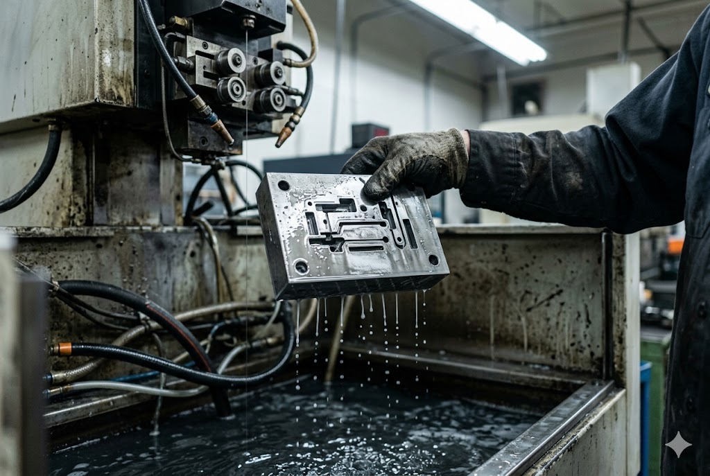
Wire EDM is the standard production method for punches, dies, and mold inserts because it cuts matched profiles in hardened steel with clearances as tight as 0.01mm, in a single setup, with no repositioning error. The punch and die can be cut from the same stack of material, ensuring the profiles are geometrically identical.
Why Punch and Die Sets Belong on Wire EDM
A stamping die requires the punch profile and the die opening to be matched within a few hundredths of a millimeter. Too much clearance and the stamped part tears rather than shearing cleanly. Too little and the punch seizes in the die.
Wire EDM produces both components from the same programmed path. The punch blank and die blank are stacked or cut sequentially. Geometric error between them is essentially zero because the same wire path defines both profiles. No other process achieves this level of matched geometry in hardened material without secondary grinding. As CAM Tech EDM documents for progressive stamping dies 3, wire EDM allows exact die clearances that last longer, and distortions from heat treatment are also eliminated since punches and dies can be processed after hardening.
Mold Inserts: Wire EDM vs. Sinker EDM
Mold inserts present a choice: wire EDM for through-profiles, sinker EDM for blind cavities. Understanding the difference matters.
| Feature Type | Wire EDM | Sinker EDM |
|---|---|---|
| Through-holes and slots | Excellent | Not applicable |
| Blind pockets and cavities | Not applicable | Excellent |
| Internal sharp corners (through) | Excellent | Good |
| 3D curved surfaces | Not applicable | Limited by electrode |
| Hardened material | Excellent | Excellent |
| Setup cost | Low (no electrode) | Higher (electrode per shape) |
The distinction between these two processes is fundamental. According to a detailed comparison of sinker EDM and wire EDM from MC Machinery 4, wire EDM cannot produce blind features and is best for profile cutting with through-holes, while sinker EDM can produce blind features including holes and cavities that don't open on the bottom end.
Material Hardness Is Not a Constraint
One of the most valuable properties of wire EDM for tooling is hardness independence. The process erodes material electrically, not mechanically. H13 at 50 HRC and H13 at 54 HRC cut at essentially the same speed. D2 tool steel at 60 HRC is no slower than annealed D2.
This means the correct manufacturing sequence is: rough machine in the soft state → heat treat to final hardness → wire EDM to final profile and dimension. There is no need to leave grinding stock. The wire EDM cut is the final operation.
Tolerances Achievable in Tooling Production
| Operation | Typical Tolerance | Surface Finish (Ra) |
|---|---|---|
| Roughing cut (single pass) | ±0.015mm | ~2.5 µm |
| Semi-finish (second pass) | ±0.008mm | ~1.2 µm |
| Finish skim (third pass) | ±0.003mm | ~0.4 µm |
| Precision skim (fourth pass) | ±0.001mm | ~0.2 µm |
For most tooling applications, a three-pass sequence — rough, semi-finish, finish — achieves ±0.003mm and Ra 0.4µm, which is adequate for punch profiles, die openings, and mold insert interfaces without any hand polishing on the cut faces.
What Part Geometries Make Wire EDM the Most Cost-Efficient Cutting Method?
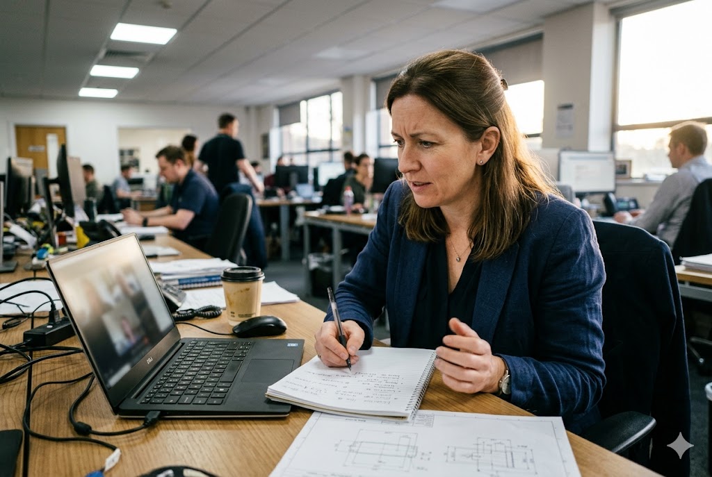
Cost efficiency in wire EDM is directly tied to setup simplicity. We tell customers: if your part can be fixtured once and the wire can complete the full profile without repositioning, wire EDM is likely your most cost-effective precision option.
Wire EDM is most cost-efficient for through-contour profiles in hardened materials, small-batch punch and die sets, thin-wall features where milling would cause deflection, parts with multiple internal sharp corners, and any geometry that would otherwise require a combined milling-plus-grinding sequence.
The Setup Cost Advantage
Unlike milling, wire EDM requires no dedicated tooling per geometry. There are no end mills to select, no tool changers to program, and no tool-change stops. The wire itself is the tool. A new geometry is a new CNC program — and programming cost is the same whether it is a simple rectangle or a 48-point spline curve.
This makes wire EDM uniquely suited to prototypes and short production runs. The first part and the hundredth part have the same per-unit cost structure because setup overhead does not scale with volume. This advantage is well-documented — a comprehensive wire EDM machining overview from Xometry 5 notes that the non-contact process eliminates tool deflection, ensuring the cut stays on the programmed path with tolerances typically in the range of ±0.002–0.01mm.
Geometries With the Best Cost-to-Precision Ratio
| Geometry Type | Why Wire EDM Wins |
|---|---|
| Extrusion dies (H13 tool steel) | Complex profile at ±0.01mm, single setup, no cumulative fixture error |
| Fine blanking punches | Hardened, matched profiles, no grinding stock needed |
| Precision slots in hardened plates | No milling chatter, no deflection, no tool wear |
| Repeating angular features (fins, teeth) | Same path repeated with angular offset — minimal extra programming |
| Taper punches (up to 30°) | UV-axis taper cutting in a single uninterrupted pass |
Thin Walls: Where Wire EDM Outperforms Milling on Risk
When a wall is thin — below 3mm — milling becomes a deflection problem. The cutting force pushes the wall, and the wall springs back, leaving a surface that is neither flat nor dimensioned correctly. Conventional fixes involve slower feeds, more passes, and fixture supports that add setup time.
Wire EDM applies zero mechanical cutting force. Thin walls stay in position throughout the cut. Wall sections as thin as 0.5mm are routinely achievable. As Infinity EDM explains when outlining the key signs your project needs wire EDM 6, the thermal energy that removes material is highly localized, so thin walls maintain their intended dimensions and delicate features remain intact even where conventional machining would cause deflection. Below 0.5mm, the dielectric flushing pressure — not the wire — becomes the deflection risk, and this requires careful nozzle positioning.
When Wire EDM Stops Being Cost-Efficient
Wire EDM is a through-cut process. The wire enters from the top and exits from the bottom. Anything that requires a feature that does not pass all the way through the part — a pocket, a shoulder, a 3D curved surface — belongs to a different process. Hybrid parts that need both wire EDM profiles and milled pockets use both processes in sequence, with wire EDM last to preserve the precision features.
Parts with very high aspect ratios — cut depth greater than 80mm in a narrow slot — require extra attention. Wire tension causes a measurable bow in the kerf at mid-height, a phenomenon known as barreling. The slot is slightly wider at mid-height than at top or bottom. This requires taper compensation in the CNC program and intermediate skim passes. Modern Machine Shop's coverage of taper cutting accuracy 7 describes how volumetric taper compensation software adjusts the wire angle to counteract overburn conditions — and why these corrections must be explicitly programmed. Most standard quotation processes do not flag this automatically — buyers sourcing parts with deep narrow slots should raise this point explicitly with any supplier.
Are There Shapes That Look Suitable for EDM but Are Better Made Another Way?
This is the question we wish more buyers asked before placing orders. Misrouting a part to wire EDM does not always fail outright — sometimes it simply costs more, takes longer, or delivers a result that requires extra finishing. The shapes below are the most common traps.
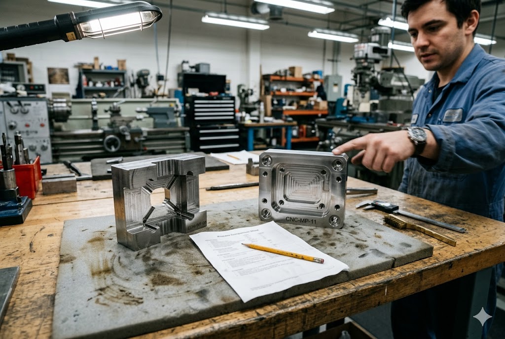
Shapes that appear suited to wire EDM but are better made another way include blind pockets, 3D curved surfaces, parts needing threaded holes, geometries requiring multiple plane setups, and very high-aspect-ratio slots where barreling error will be flagged on CMM inspection.
Blind Features: The Most Common Misrouting
A blind pocket — any cavity that does not pass all the way through the workpiece — cannot be cut by wire EDM. The wire has nowhere to exit. Buyers sometimes assume EDM means all EDM processes, but wire EDM and sinker EDM are entirely different machines with entirely different capabilities.
| Feature | Wire EDM | Sinker EDM | CNC Milling |
|---|---|---|---|
| Through-slot or through-profile | ✔ Best choice | ✘ | ✔ (if tolerances allow) |
| Blind pocket or cavity | ✘ | ✔ Best choice | ✔ (roughing + finishing) |
| Threaded hole | ✘ | ✘ | ✔ |
| 3D contoured surface | ✘ | Limited | ✔ (5-axis) |
| Through-taper profile | ✔ (up to 30°) | ✘ | ✔ (limited by tool) |
A WayKen comparison of sinker EDM and wire EDM 8 clarifies this directly: sinker EDM is suitable for fabricating thin walls, blind cavities, and cross-sections it does not necessarily cut all the way through — whereas wire EDM is limited to profiles where the wire can enter and exit the full thickness of the part.
3D Surfaces and Multi-Plane Features
Wire EDM operates in two primary axes — X and Y — with UV-axis taper capability. It cannot produce a curved surface in the Z direction. A cam lobe, a turbine blade profile, or a forming die with a 3D contoured face all require multi-axis milling or grinding.
Parts that combine through-profiles with 3D features — a mold insert with both a wire-cut gate opening and a curved cavity surface — need both processes. The sequencing matters: CNC milling first, then wire EDM last. Reversing the order risks damaging wire EDM precision surfaces during clamping for milling. A practical guide to when wire EDM is the right process from Jennison Corp 9 reinforces this: wire EDM excels at cutting D2 tool steel at 60+ HRC with the same ease as softer materials, but cannot produce blind holes or 3D internal features without a secondary process.
High-Aspect-Ratio Slots: The Hidden Dimension Problem
A slot that is 2mm wide and 100mm deep looks like a wire EDM job on a 2D drawing. In cross-section, it is a simple rectangle. But in practice, the wire bows at mid-height due to wire tension. The kerf at 50mm depth is measurably wider than at 0mm or 100mm.
This barreling error is invisible on a 2D drawing review and on a surface plate check. It only shows up on CMM inspection at multiple Z-heights. Research on high-aspect-ratio thin-walled structures in D2 steel cut by wire EDM 10 confirms that structures with a very high aspect ratio exhibit measurable deflection at their free ends regardless of fin height — a finding that directly applies to deep-slot geometry. Buyers specifying such slots should ask explicitly: does your quote include taper compensation and intermediate skim passes for the full cut depth? If the supplier does not understand the question, that is an informative answer.
Parts That Need Both Processes
The cleanest solution for many precision parts is a defined split: CNC milling handles the bulk material removal, shoulder features, threaded holes, and 3D surfaces; wire EDM handles the through-profiles, tight corner features, and matched tooling pairs. Treating these as competing processes is the wrong frame. Treating them as complementary steps — each doing what it does best — produces the part that the drawing actually calls for.
Conclusion
Wire EDM is a precision tool with well-defined boundaries. Match the geometry to the process — through-profiles, tight corners, hardened tooling — and the results are exceptional. Send the wrong shape to the wrong machine and the cost and timeline both suffer.
Footnotes
1. How wire EDM achieves tight internal corner radii that no end mill can replicate. ↩︎
2. Why zero cutting forces in wire EDM enable machining of hardened and thin-walled parts. ↩︎
3. Wire EDM advantages for progressive stamping die production after heat treatment. ↩︎
4. Key capability difference: wire EDM for through-profiles, sinker EDM for blind cavities. ↩︎
5. Overview of wire EDM tolerance ranges and non-contact process benefits. ↩︎
6. How wire EDM's non-contact cutting preserves thin walls and delicate features. ↩︎
7. Volumetric taper compensation software corrects overburn in deep wire EDM cuts. ↩︎
8. Sinker EDM handles blind cavities and cross-sections; wire EDM cuts full-thickness profiles. ↩︎
9. Wire EDM cuts hardened D2 and tool steels efficiently but cannot produce 3D blind features. ↩︎
10. Peer-reviewed study on deflection in high-aspect-ratio thin structures cut by wire EDM. ↩︎



