 Skip to main content Skip to footer
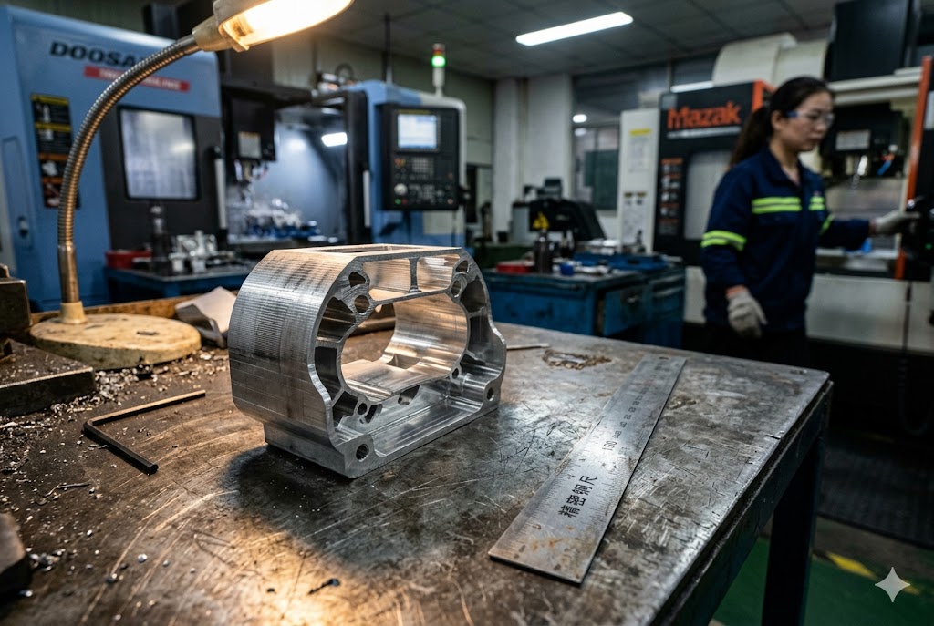
Every week, our team reviews drawings with thin-walled features that suppliers across China flag at the last minute — after the PO is placed. We've seen parts scrap, deadlines slip, and buyers absorb costs that a single DFM conversation 1 could have prevented.
Wire EDM machined parts from China face strict wall thickness limitations: the practical minimum in the XY plane is 0.5mm for slow-wire machines, while fast-wire shops require thicker walls to avoid deflection. Material matters too — aluminum needs 0.8mm minimum, steel 1.2mm, and titanium 1.5mm for reliable results.
If you're sourcing wire EDM parts, these numbers belong in your RFQ checklist. Here's what you need to know before you send your next drawing.
What Is the Minimum Wall Thickness a Wire EDM Supplier Can Reliably Cut?
When our engineers run DFM reviews on incoming drawings, thin walls are the single most common flag we raise before quoting. Most buyers don't know the threshold — and most suppliers don't volunteer it upfront.
The reliable minimum wall thickness for wire EDM in the XY plane is 0.5mm. Below this, wire tension and flushing pressure cause the wall to deflect during cutting, introducing dimensional errors that skim passes cannot fix. Any wall under 0.5mm should be explicitly flagged at the RFQ stage.
Why 0.5mm Is the Industry Threshold
Wire EDM does not apply mechanical cutting force. The wire never touches the workpiece. But two physical forces still act on thin walls during machining — and both matter.
The first is wire tension. The wire is kept under tension throughout the cut. On a thin wall, that tension causes the wall to flex slightly as the wire passes. The result is a cut that reads in-tolerance at the start and end of the pass but is out of tolerance in the middle.
The second is dielectric flushing pressure. The machine jets high-pressure water along the wire to flush eroded particles from the cut zone. On walls under 0.5mm, this jet applies enough lateral force to deflect the wall — and that deflection is invisible until the part is measured.
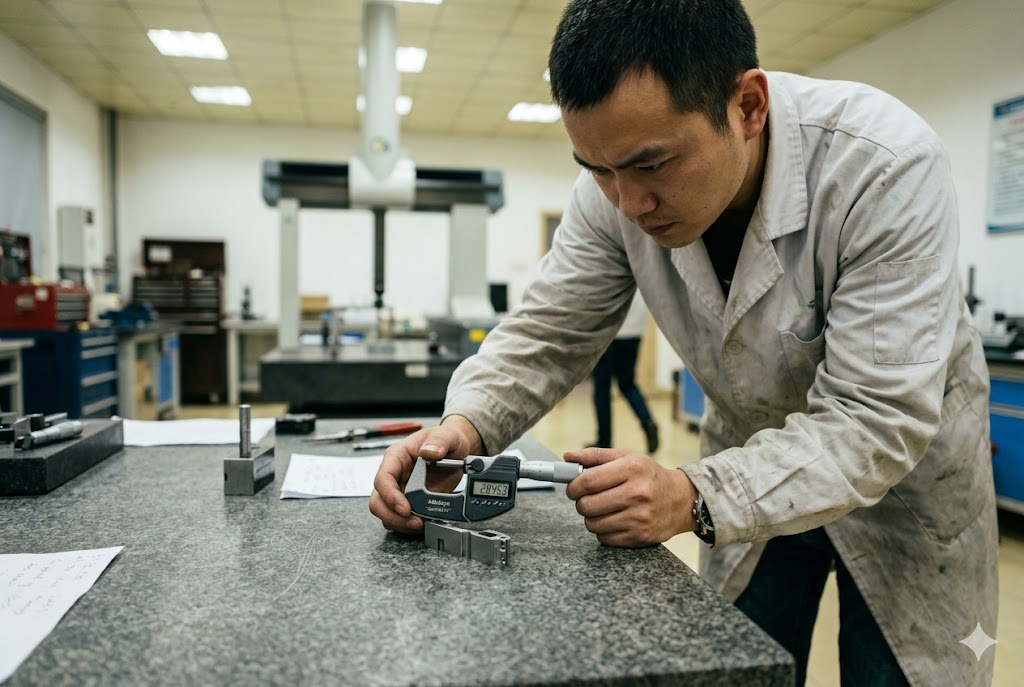
Both mechanisms are well understood in precision shops. The 0.5mm threshold is the standard screening criterion Chinese suppliers use in DFM review for EDM 2. If your drawing has walls thinner than this, you need a conversation with the supplier before production starts — not after.
Material-Specific Minimums
Different materials behave differently under flushing force and wire tension. A steel wall resists deflection better than aluminum at the same thickness. Titanium is stiffer still, but its chip-welding behavior introduces other risks.
| Material | Minimum Recommended Wall Thickness | Notes |
|---|---|---|
| Aluminum | 0.8mm | Low stiffness; flushing pressure causes deflection easily |
| Steel (tool steel / stainless) | 1.2mm | Better stiffness; still needs DFM review at thin sections |
| Titanium | 1.5mm | Zero cutting force makes EDM preferred; thermal risk at thin walls |
| Inconel / high-temp alloys | 1.5mm+ | Preferred over CNC milling; thin walls need slow-wire only |
For parts with length-to-thickness ratios above 15:1, the risk of deflection beyond tolerance rises sharply — regardless of material. If your drawing has any feature in this range, put it in your supplier discussion before quoting.
Absolute Minimums in Research vs. Production
Academic research has demonstrated wire EDM walls as thin as 117μm (0.117mm) in D2 tool steel at heights of 10–30mm. These results exist. But they require carefully optimized machine parameters, custom fixturing, and multiple test runs to establish a stable process. They are not achievable at a standard Chinese fast-wire shop with standard settings.
For production parts, 0.5mm is the floor. Anything below this should be treated as a special process requiring explicit supplier qualification, not a standard shop capability.
Does Thin Wall Thickness Increase the Risk of Part Distortion During Wire EDM?
We've received parts back from production that passed first-article inspection at the top and bottom of the wall — but showed a visible belly at mid-span when measured with a CMM. That's not a machine calibration issue. That's a flushing problem caused by a wall that was too thin for the cut height.
Yes, thin walls significantly increase the risk of distortion during wire EDM. Two distinct deflection mechanisms operate on different axes: walls under 0.3mm in height direction deflect from water jet flushing, while walls under 0.5mm in XY plane may vibrate during cutting. Both cause dimensional error.
Two Deflection Mechanisms — Different Axes, Different Fixes
Most buyers think about wall thickness as a single dimension. In practice, thin-wall distortion in wire EDM has two distinct root causes that act on different axes. Understanding both is important when reviewing your drawing with a supplier.
Axis 1: Height-Direction Deflection (Z-axis)
When a tall, thin wall is being cut, the dielectric jet runs along the full height of the cut. If the wall is under 0.3mm thick in the height direction, the jet pressure alone is enough to push the wall off its nominal position. The wire then cuts a path that follows the deflected wall — not the intended geometry.
The result is a barrel-shaped profile: the wall is in tolerance at the top and bottom where the jet enters and exits, but bulges outward at mid-span. A straightness callout of ±0.005mm can pass at both ends while the mid-span exceeds ±0.02mm. The part passes visual inspection and fails CMM measurement aligned with ISO 10360 3.
Axis 2: XY-Plane Vibration
Walls under 0.5mm in the XY plane can act like a thin blade. As the wire approaches and the spark gap closes, the electrical discharge creates micro-vibrations in the workpiece. In a wall with normal thickness, this is damped by the surrounding material. In a thin wall, the energy has nowhere to dissipate — and the wall vibrates in sync with the discharge frequency.
This produces a surface that is visually smooth but dimensionally inconsistent along its length.
How Heat Treatment Sequencing Affects Thin-Wall Stability
For tool steel parts, distortion risk is not limited to the cutting step. Heat treatment before EDM releases residual stress from the raw material — and if that stress is released during the EDM cut rather than before it, the part moves during machining.
The correct sequence is:
| Step | Process | Purpose |
|---|---|---|
| 1 | Stress Relief | Remove residual stress from raw stock |
| 2 | Rough Wire EDM | Cut near-net shape before hardening |
| 3 | Hardening | Harden to target HRC |
| 4 | Finish Wire EDM | Final pass to achieve drawing tolerances |
Suppliers who recommend skipping the rough EDM pass before hardening should be asked for distortion data on comparable parts before you approve their process plan. The correct sequence is well established and any qualified precision shop should be able to explain it.
Tall Sections and Poor Flushing
Poor flushing in tall or thin sections leads to a specific failure mode: secondary arcing. When eroded particles are not evacuated from the cut zone, they re-enter the spark gap and cause secondary discharges. This creates surface pitting, uneven material removal, and a barrel-shaped cut profile.
For tall, thin sections, the fix is either splitting the part into thinner subplates that are bonded or fastened after machining, or hollowing the center of the part to reduce the total cut height. Both approaches can reduce EDM cycle time by up to 60% — but both require design changes that most Chinese suppliers will not proactively suggest. If your part has tall thin walls, raise this with your supplier at the DFM stage.
How Should I Redesign My Part to Avoid Wall Thickness Issues in Wire EDM?
Our sourcing team spends a meaningful portion of every project in DFM conversations before a single part is cut. The questions buyers ask us most often are not about tolerance — they're about what changes to the drawing could have prevented the problem entirely.
To avoid wall thickness issues in wire EDM, redesign thin walls to exceed material-specific minimums, keep length-to-thickness ratios below 15:1, maintain inter-slot walls at least 3× the wire diameter, and split tall thin sections into bonded subplates where possible. Adding 0.1mm to target slot widths accounts for wire kerf.
Key Design Rules for Wire EDM Thin-Wall Features
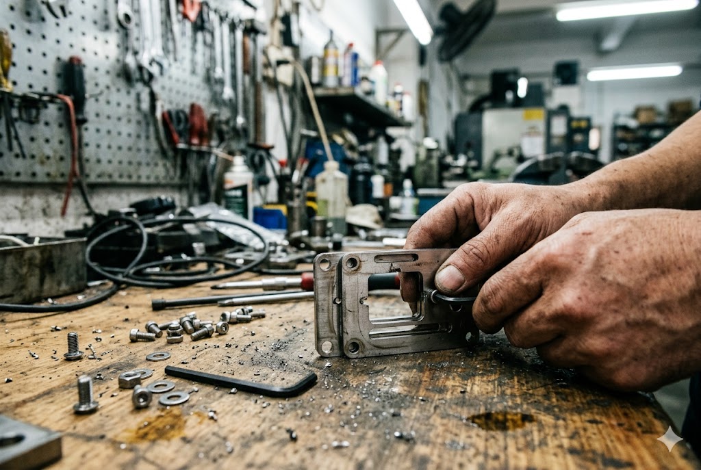
Good DFM for wire EDM comes down to a small set of rules. Most of them are straightforward once you know the numbers.
Rule 1: Wall Thickness vs. Material Minimums
Check every thin-wall feature on your drawing against the material-specific threshold. If your wall is at or below the minimum, you have two options: increase the wall thickness on the drawing, or qualify a supplier capable of the special process.
Rule 2: Length-to-Thickness Ratio
Any wall with a length-to-thickness ratio above 15:1 4 should be reviewed carefully. A wall that is 0.8mm thick and 15mm long is right at the boundary. A wall that is 0.8mm thick and 25mm long is almost certain to deflect beyond tolerance in a conventional setup.
| L/T Ratio | Risk Level | Recommended Action |
|---|---|---|
| < 10:1 | Low | Standard wire EDM process |
| 10:1 – 15:1 | Medium | Discuss fixture design with supplier |
| > 15:1 | High | Redesign or split into subplates |
Rule 3: Inter-Slot Wall Thickness
For parts with multiple parallel slots — common in filters, heat exchangers, and precision fixtures — the wall between adjacent slots must be at least 3× the wire diameter 5. With a standard 0.25mm wire, this means a minimum inter-slot wall of 0.75mm.
It's also good practice to add 0.1mm to the target slot width on the drawing to account for wire kerf. A drawing that calls out the finished slot width as-cut will produce parts that are consistently narrow unless the supplier accounts for kerf — and not all of them do.
Rule 4: Splitting Tall Thin Sections
If your part has a wall that is both thin and tall — say, under 0.5mm thick at a height of 20mm or more — the most reliable fix is to split the feature into two thinner sections that are bonded or mechanically fastened after EDM. This reduces the effective cut height, improves flushing, and eliminates the barrel-profile risk entirely.
This redesign also tends to reduce cycle time significantly. Shorter cut passes flush more effectively, require fewer skim passes, and produce more consistent surface finish. The trade-off is an additional assembly step — which is often cheaper than the scrap rate on a difficult single-piece design.
What to Put on Your Drawing
A well-prepared drawing communicates process requirements, not just geometry. For thin-wall wire EDM parts, consider adding:
- Minimum wall thickness callout at each thin-wall feature
- Straightness tolerance on tall wall sections (not just dimensional tolerance)
- Slot width with kerf allowance noted
- Process note: "Slow-wire EDM required for walls ≤ 0.5mm"
Can Slow-Wire EDM Handle Thinner Walls Than Fast-Wire EDM for Precision Parts?
One of the most common sourcing mistakes we see is buyers leaving machine selection to the supplier's discretion on thin-wall parts. The gap between slow-wire and fast-wire capability on thin walls is wider than most buyers expect — and it matters to your scrap rate.
Yes, slow-wire EDM handles thinner walls more reliably than fast-wire EDM. Fast-wire machines run at 8–10 m/s wire speed, generating significantly higher flushing turbulence than slow-wire machines running below 0.2 m/s. The 0.5mm threshold safe on slow-wire consistently causes wall deflection and scrap on fast-wire machines cutting the same part.
The Core Difference: Wire Speed and Flushing Turbulence
Fast-wire EDM — sometimes called WEDM-HS in China — runs the wire at high speed in a reciprocating motion. The wire travels at 8–10 m/s, is reused across multiple passes, and is the dominant machine type in lower-cost Chinese shops due to its lower operating cost.
Slow-wire EDM — WEDM-LS — runs the wire as a single-pass consumable at speeds below 0.2 m/s. The wire is never reused. The process is far more stable, produces better surface finish, and critically, generates much lower flushing turbulence.
For thin walls, flushing turbulence is the key variable. A fast-wire machine generating high turbulence applies significantly more lateral force to a thin wall than a slow-wire machine. The 0.5mm wall that holds dimension reliably on a slow-wire machine will deflect and scrap consistently on a fast-wire machine cutting the same part 6.
What This Means for Sourcing in China
The majority of Chinese wire EDM shops — particularly smaller shops in Dongguan, Shenzhen, and Hangzhou industrial zones — operate primarily fast-wire machines. Slow-wire capacity exists in China, but it is concentrated in higher-tier precision shops and commands a price premium.
| Machine Type | Wire Speed | Flushing Turbulence | Min. Reliable Wall | Typical Accuracy |
|---|---|---|---|---|
| Fast-wire (WEDM-HS) | 8–10 m/s | High | ~0.8mm | ±0.01–0.02mm |
| Slow-wire (WEDM-LS) | < 0.2 m/s | Low | ~0.5mm | ±0.003–0.005mm |
If your part has walls at or below 0.5mm, specify slow-wire as a process requirement on your drawing. Do not leave machine selection to the supplier. A supplier operating a fast-wire shop has a commercial incentive to run your part on the machine they have — not the machine your part needs. Understanding the technical distinctions between WEDM-LS and WEDM-HS 7 helps buyers write more precise process notes and evaluate supplier capability before placing an order.
Titanium and Inconel Thin-Wall Parts
Thin-walled titanium and Inconel aerospace brackets 8 are a case where slow-wire EDM is not a preference — it is the mandated process. The zero cutting force of wire EDM is precisely why these parts cannot be reliably produced on CNC milling below 0.5mm wall thickness. But the absence of cutting force does not mean absence of process-induced stress: thermal effects from the spark still affect thin walls, and slow-wire's finer spark energy control reduces heat-affected zone depth compared to fast-wire.
For Ti-6Al-4V surgical components 9 and Inconel aerospace brackets with wall thickness under 0.5mm, slow-wire EDM is routinely used in qualified shops and has a strong track record of producing straight, uniform profiles. These parts are not exotic — but they require a supplier with the right equipment and process discipline.
Conclusion
Wall thickness in wire EDM is not a minor detail — it determines whether your part is producible at the tolerance your drawing requires. Know your material minimums, specify slow-wire when walls are thin, flag inter-slot walls at the RFQ stage, and never leave machine selection to supplier discretion on precision thin-wall parts 10.
Footnotes
1. A complete guide to DFM principles, checklists, and process alignment for CNC manufacturing. ↩︎
2. Wikipedia overview of rule-based DFM analysis specific to EDM processes and wall feature design. ↩︎
3. Definition and examples of ISO 10360 standards governing CMM accuracy and dimensional verification. ↩︎
4. CNC design guidelines covering wall thickness ratios, pocket depth, and DFM rules to reduce scrap risk. ↩︎
5. Explains when to use wire cut EDM vs. CNC machining, including inter-slot wall minimums and kerf allowances. ↩︎
6. Detailed technical comparison of fast-wire vs. slow-wire EDM: wire speed, flushing, accuracy, and cost. ↩︎
7. Explains machine type differences between WEDM-LS, WEDM-MS, and WEDM-HS for supplier evaluation. ↩︎
8. EDM titanium machining guide covering recast layer control, heat-affected zone, and aerospace applications. ↩︎
9. NCBI peer-reviewed study on WEDM process parameters for machining Ti-6Al-4V titanium alloy. ↩︎
10. Practical comparison of fast, medium, and slow wire EDM speeds with accuracy and cost trade-offs. ↩︎



