 Skip to main content Skip to footer
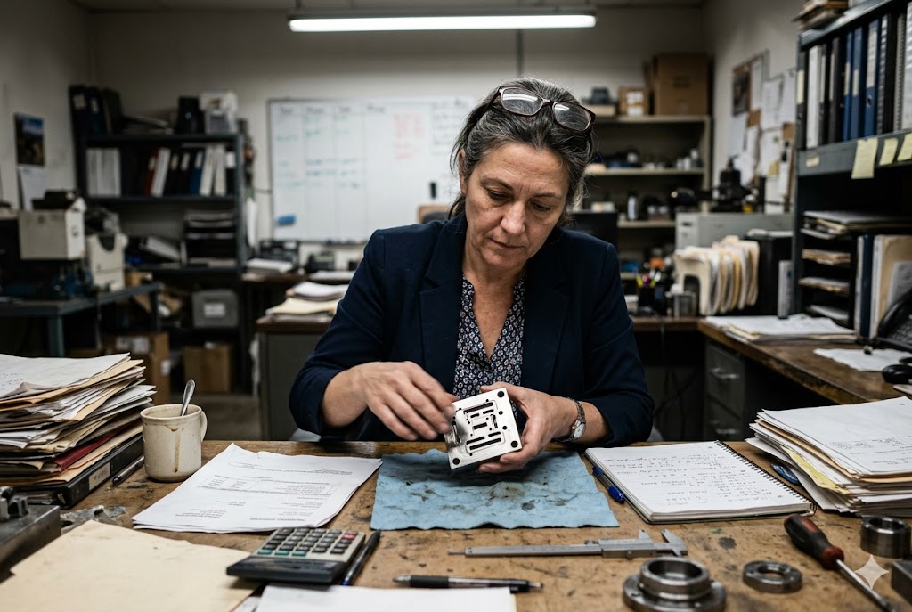
Every week, our team reviews parts that came back out of tolerance. More often than not, the root cause is the same: the wrong heat treatment sequence.
Heat treatment condition directly affects wire EDM accuracy. Cutting hardened and tempered steel (58–62 HRC) after heat treatment minimizes distortion. Cutting in the annealed condition and hardening afterward shifts features out of tolerance. The correct sequence prevents dimensional errors that cannot be corrected later.
If you are specifying EDM parts on a drawing, or managing a supplier doing this work, the sequencing decision matters more than the cutting parameters. Here is what you need to know.
Should Heat Treatment Be Done Before or After Wire EDM to Minimize Distortion?
We see this question every time a client sends us a new die or mold project. Getting the sequence wrong is costly, and fixing it after the fact is usually not possible.
For tool steel dies and molds, finish wire EDM should be done after hardening and tempering, not before. Hardening after EDM shifts cut features out of tolerance due to heat treatment distortion. The standard sequence is: stress relief → rough EDM → harden and temper → finish EDM trim passes.
Why Sequence Matters More Than Cutting Speed
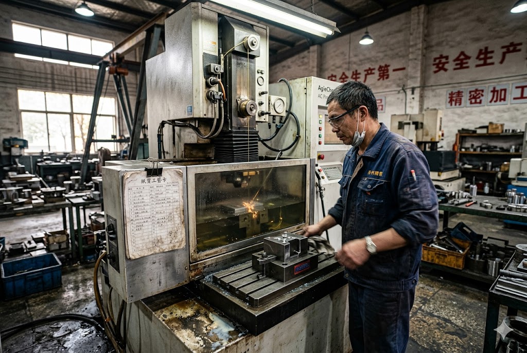
Wire EDM 1 applies no cutting force. That is one of its main advantages. But no cutting force does not mean no dimensional risk. The real threat is what happens to the steel's internal stress state before, during, and after cutting.
When you EDM a part in the annealed condition, the cut dimensions look correct on the machine. Then the part goes to heat treatment. Hardening involves heating to austenitizing temperature, quenching, and tempering. Each of these steps introduces stress and causes the steel to move. Features that were on tolerance before hardening are now shifted.
By how much? It depends on section thickness, part geometry, and steel grade. But even on a well-controlled D2 die plate, you can expect 0.02–0.10 mm of movement after through-hardening. For a die cavity holding ±0.01 mm, that is a rejection.
The Optimal Sequence for High-Precision Tool Steel
| Step | Operation | Purpose |
|---|---|---|
| 1 | Stress relief anneal | Remove machining stresses before EDM |
| 2 | Rough wire EDM | Remove bulk material, leave 0.1–0.3 mm stock |
| 3 | Harden and temper | Achieve final hardness (e.g., 58–62 HRC) |
| 4 | Finish wire EDM trim passes | Correct distortion, hit final tolerance |
This split approach is the industry standard for precision tooling. Roughing before hardening saves expensive EDM time. Finish cutting after hardening corrects any distortion introduced by the thermal cycle.
The Role of Residual Stress from Quenching
Quenching locks stress into the steel 2. Tempering reduces it, but never eliminates it completely. When wire EDM removes material from a hardened workpiece, it releases some of that locked-in stress. The part can spring or bow, especially in thin sections or asymmetric profiles.
This is why double tempering is standard practice for tool steels like D2 and H13. The first temper converts most of the as-quenched martensite. The second temper relieves stress introduced during the first temper cycle. Parts that are only single-tempered carry higher residual stress into the EDM operation, increasing distortion risk.
What About Precipitation-Hardening Stainless Steels?
For grades like 17-4 PH or Corrax 3, the rule is different. EDM can be performed in the solution-annealed condition without impairing toughness at that stage. However, aging after EDM reduces toughness. The correct sequence for PH stainless is: age first, then EDM. This preserves the final mechanical properties of the finished part.
| Steel Type | Recommended EDM Condition | Notes |
|---|---|---|
| D2, O1, H13 (tool steel) | Hardened and tempered | Finish EDM after hardening |
| 17-4 PH, Corrax (PH stainless) | Aged condition | Age first, EDM after |
| P20, NAK80 (pre-hardened) | As-supplied (~30–40 HRC) | No additional heat treatment needed |
How Much Dimensional Change Should I Expect After Quench and Temper on EDM Parts?
In our experience managing heat treatment for export orders to the US, dimensional movement after quench and temper is one of the most frequent sources of disputes between buyers and suppliers. The numbers below are what our engineering team tracks on production runs.
Dimensional change after quench and temper depends on steel grade, section thickness, and part geometry. Through-hardened tool steels typically move 0.02–0.10 mm on critical features. Asymmetric or thin sections move more. Anticipating this movement and leaving EDM stock for a finish pass is the correct engineering response.

Typical Movement by Steel Grade
Not all steels move the same amount. High-alloy tool steels with good hardenability and lower martensite start temperatures tend to move more during quenching. Carbon steels quenched in water move more than air-hardened high-speed steels.
| Steel Grade | Hardening Method | Typical Dimensional Movement |
|---|---|---|
| D2 | Air cool | 0.02–0.05 mm on flat features |
| O1 | Oil quench | 0.05–0.10 mm, direction-dependent |
| H13 | Air/gas quench | 0.02–0.04 mm with good fixturing |
| A2 | Air cool | 0.02–0.05 mm, relatively stable |
| 1.2343 / H11 | Air/gas quench | Similar to H13 |
These figures are for well-controlled vacuum heat treatment 4. Salt bath or atmospheric furnace hardening produces greater variation.
Factors That Increase Movement
Section thickness asymmetry is the biggest driver of unexpected movement. A die plate with a deep pocket on one side and a flat back will cool unevenly. Uneven cooling means uneven martensite formation. Uneven martensite formation means the part bends toward the faster-cooling side.
Other factors that increase movement:
- Thin walls below 3 mm adjacent to EDM slots
- Long, narrow punch or blade profiles
- Uneven carbide distribution in high-carbon steels (e.g., D2 with banded carbides)
- Single tempering instead of double tempering
How to Account for It in Your Drawings
If you are specifying an EDM part that will be hardened, add a note to your drawing: "Rough machine to 0.15 mm stock on EDM surfaces. Finish EDM after hardening and double tempering to final dimensions." This tells the supplier exactly what sequence you expect. It also protects you if the finished part is out of tolerance due to wrong sequencing.
Our team adds this kind of note to supplier drawings as part of our standard project management process. Clients who have experienced heat treatment distortion problems before appreciate having this documented before production starts.
Does Hardened Steel Require Different Cutting Parameters to Hold Tight EDM Tolerances?
When we calibrate cutting parameters for a new order, the first question our process engineers ask is: what is the material condition? Hardened steel and annealed steel behave differently in the spark gap, and using the same parameters for both is a common mistake.
Yes, hardened steel requires different wire EDM cutting parameters. Hardening changes the electrical conductivity and thermal diffusivity of the workpiece. Parameters calibrated on annealed test stock produce dimensional deviations on hardened production parts. Separate parameter sets are needed for each metallurgical condition.
Why Electrical and Thermal Properties Change with Hardness
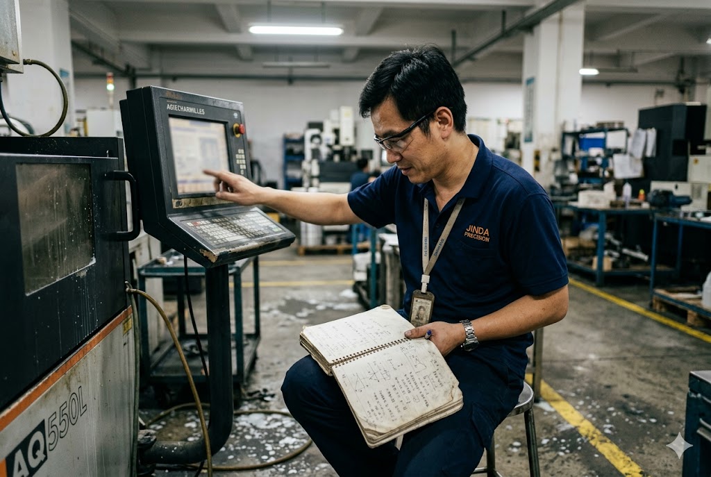
Wire EDM removes material by electrical discharge 5. The spark gap, energy per pulse, and material removal rate are all functions of the workpiece's thermal and electrical properties. These properties change when steel is hardened.
Annealed steel has a more uniform, coarser microstructure. Hardened steel has a fine martensitic matrix with different thermal diffusivity. The spark energy dissipates differently in each condition. If you run the same pulse energy settings on hardened steel that you calibrated on annealed stock, the effective spark gap changes. The cut geometry shifts. Tolerances suffer.
Cutting Parameters to Adjust for Hardened Workpieces
| Parameter | Annealed Condition | Hardened Condition (58–62 HRC) |
|---|---|---|
| Pulse energy (on-time) | Standard | Reduce by 10–20% for finish passes |
| Flushing pressure | Standard | Increase slightly — debris removal is critical |
| Wire tension | Standard | Increase for tight corner accuracy |
| Number of trim passes | 2–3 | 3–4 for tight tolerances |
| Feed rate | Higher | Lower — prioritize surface quality |
Microcracking Risk in Hardened High-Carbon Steels
High-carbon tool steels like D2 and O1 6 cut in the hardened condition are prone to microcracking in the recast layer. The martensitic matrix is brittle. The EDM process creates a thin layer of re-solidified material at the cut surface called the white layer or recast layer. In hardened high-carbon steel, this layer is under tension and can crack.
The risk is highest in as-quenched parts — steel that has been hardened but not yet tempered. As-quenched martensite carries maximum residual tensile stress. Even the low thermal input of a finishing pass can initiate micro-cracks. These cracks can propagate into the base metal and cause part rejection at inspection.
The fix is simple: always temper before EDM. Double tempering is strongly preferred for D2, H13, and similar grades. Proper tempering reduces residual stress in the martensite, reduces microcracking risk, and produces a more consistent white layer at the cut edge.
The Recast Layer and Final Dimensions
Every EDM cut leaves a recast layer 7. Annealed workpieces produce a thicker, less uniform recast layer because the lower hardness and higher thermal conductivity variation affect how re-solidified material forms at the edge. Tempered martensite produces a thinner, more chemically consistent recast layer.
For toleranced dimensions, the recast layer thickness must be accounted for. On a finish-trimmed hardened surface, the recast layer is typically 2–10 µm. If your drawing calls for a surface to be ground after EDM, the recast layer is removed in that operation. If the EDM surface is a final surface, the dimensional offset introduced by the recast layer needs to be included in the cutting program offsets.
How Do I Specify the Correct Material Condition on My Technical Drawing for EDM Parts?
Our engineers review hundreds of drawings per year from US and Canadian clients. Incomplete material condition notes are one of the top causes of supplier misunderstanding and out-of-tolerance deliveries. A clear drawing note takes two minutes to write and can prevent weeks of rework.
To specify material condition on a technical drawing for EDM parts, include the steel grade, heat treatment condition, target hardness range (HRC), and the EDM sequencing note. For example: "D2 tool steel, vacuum hardened and double tempered to 60–62 HRC before finish EDM. Rough EDM stock 0.15 mm on all EDM surfaces prior to hardening." This eliminates ambiguity for the supplier.

What to Include in Your Drawing Notes
A complete material and process specification for an EDM part should cover four things: material grade, heat treatment condition, hardness requirement, and process sequence. Most drawings include the first two. Fewer include the last two. All four are needed.
| Note Element | Example | Why It Matters |
|---|---|---|
| Material grade | "D2 tool steel per ASTM A681 8" | Prevents substitution with cheaper grades |
| Heat treatment condition | "Vacuum hardened and double tempered" | Controls microstructure and residual stress |
| Hardness range | "60–62 HRC 9, minimum 3 measurements per part" | Defines acceptance criteria |
| Process sequence | "Rough EDM before hardening; finish EDM after hardening" | Prevents wrong sequencing |
Notes for Different Steel Types
For standard tool steels (D2, H13, O1, A2), the note format above works well. For pre-hardened steels like P20 or NAK80, no heat treatment sequence note is needed — these steels are supplied at working hardness (28–40 HRC) and do not require post-EDM hardening.
For precipitation-hardening stainless steels, specify the aging condition: "17-4 PH, Condition H900, aged before EDM. Do not re-age after EDM."
Tempering Temperature as a Tolerance Variable
One detail that is rarely captured in supplier documentation: tempering temperature affects distortion behavior in close-tolerance die work. Parts tempered at the lower end of the recommended range retain more residual compressive stress in the bulk material. This partially counteracts the tensile residual stress introduced by the EDM white layer.
In practice, this means the net distortion of a thin wall or punch profile depends on the exact tempering temperature, not just the final hardness. For multi-cavity dies or parts with features closer than 0.5 mm to an EDM surface, specifying a tempering temperature range of ±10°C is worth the extra line on the drawing. H13 tool steel 10 is a good example of a grade where this discipline pays off — its wide tempering range of 538–621°C gives manufacturers flexibility, but that same range means two parts at the same HRC can have meaningfully different stress states.
How Our Team Handles Drawing Reviews
When a new client sends us a part drawing, our engineers check for all four elements above. If any are missing, we flag them before sending the drawing to suppliers. This protects the client from receiving parts that are on hardness but wrong on distortion, or correct on dimensions but wrong on microstructure.
We document the agreed process sequence in the purchase order and in the quality inspection plan. Pre-shipment inspection includes hardness verification and dimensional checks on all EDM surfaces. This is the only way to confirm that the supplier followed the specified sequence and that the parts meet drawing requirements before they leave the factory.
Conclusion
Heat treatment sequence is the single biggest variable in wire EDM dimensional accuracy. Rough before hardening, finish after. Specify the full process on your drawing. Verify hardness and dimensions before shipment.
Footnotes
1. Comprehensive overview of wire EDM tolerances, capabilities, and process parameters. ↩︎
2. Peer-reviewed review of residual stress and distortion mechanisms during quench hardening of steels. ↩︎
3. Research on the aging heat treatment mechanism and mechanical properties of 17-4 PH stainless steel. ↩︎
4. Guide explaining how vacuum furnace heat treatment reduces distortion and extends tool life. ↩︎
5. Detailed guide to wire EDM cutting mechanics, spark gap physics, and achievable tolerances. ↩︎
6. Full D2 tool steel heat treatment sequence covering austenitizing, quenching, and double tempering. ↩︎
7. Industry article on how EDM thermally alters the surface, forming the white layer and recast zone. ↩︎
8. Overview of ASTM A681, the standard specification for wrought alloy tool steels including D2 and H13. ↩︎
9. Explanation of Rockwell HRC testing methodology and its application to hardened tool steels. ↩︎
10. Properties, tempering range, and applications of H13 hot work tool steel for dies and molds. ↩︎



