 Skip to main content Skip to footer

Every time we audit a new Swiss CNC supplier in China, roundness and cylindricity are the first tolerances we push on. Most factories can quote a number. Far fewer can prove they hold it across a production run of ten thousand pieces.
Swiss CNC factories in China can reliably hold roundness tolerances of ±0.005 mm and cylindricity tolerances of ±0.008 mm on micro-diameter parts, provided they use centerless-ground bar stock, properly fitted guide bushings, and temperature-controlled cutting fluid systems. Without these process controls, form tolerances degrade unpredictably in mass production.
The gap between first-article approval and ongoing production conformance is where most sourcing problems hide. The sections below break down exactly what drives that gap — and what to put in your PO to close it.
How Does Spindle Bearing Condition in a Swiss-Type Lathe Affect Roundness on Micro-Diameter Parts?
Spindle bearings rarely fail all at once. They degrade gradually, and the first sign is usually a roundness trace that starts drifting outside spec on the third shift.
Spindle bearing wear in a Swiss-type lathe directly increases radial runout of the rotating bar, which translates one-for-one into roundness error on the finished part. For micro-diameter parts under 3 mm in diameter, even 0.003 mm of bearing-induced runout can consume the entire roundness tolerance budget and leave nothing for other process variables.
Why Bar Stock Quality Sets the Ceiling
Before spindle bearings even enter the picture, the incoming bar stock sets a hard upper limit on achievable roundness. Our engineers have found that Swiss-type lathes 1 can improve total indicator runout (T.I.R.) by roughly 50% over raw stock — no more. That means bar stock with 0.05 mm T.I.R. cannot yield finished parts better than approximately 0.025 mm T.I.R., regardless of how well the spindle is maintained.
This is why we specify centerless-ground bar stock 2 classified to h7 or h8 tolerance on every PO that carries a tight roundness or cylindricity callout. Standard hot-rolled or even cold-drawn bar is simply not a suitable starting material.
Guide Bushing Clearance: The Primary Mechanical Variable
The guide bushing 3 is the structural heart of the Swiss turning process. Its job is to support the bar as close as possible to the cutting zone. When bushing clearance opens up — through wear or improper adjustment — the bar gains micro-radial freedom during the cut. That freedom produces lobing: repeating flat spots on the part OD that show up clearly on a roundness trace.
Coaxiality of the bushing must be held to ≤0.005 mm (0.0002 in) to sustain micron-level form tolerances across a production run. We verify this at supplier qualification, not just at first article.
Fixed vs. Rotary Guide Bushing: A Specification-Driven Choice
Not all Swiss lathes run the same bushing type, and the choice has direct consequences for form tolerance capability.
| Bushing Type | Best For | Roundness Capability | Trade-off |
|---|---|---|---|
| Fixed | Hard materials, tight form tolerances | ±0.005 mm or better | Friction drag on difficult materials |
| Rotary | Softer or sticky materials (e.g., aluminum, copper) | ±0.013 mm typical floor | Sacrifices roundness capability |
Fixed bushings are required for tolerances tighter than ±0.013 mm. A factory that runs rotary bushings as a default on all jobs — because it reduces tool wear and setup time — cannot meet tight form callouts. We ask suppliers to document their bushing type for each job at the setup sheet level.
Thermal Growth and Between-Shift Drift
Even a perfectly set up machine drifts. Spindle thermal growth 4 in the headstock, spindle, and tooling zone shifts the effective axis of rotation during a production run. The result: first-article parts conform, but parts produced two hours into a run or at the start of a new shift do not.
Suppliers operating in climate-controlled floor environments with temperature-regulated cutting fluid systems can manage this. Shops without these controls face chronic between-shift form error recurrence. It is a facility-level issue, not a machine-level one, and it shows up in production data — not first-article reports.
| Process Control | Impact on Roundness Stability |
|---|---|
| Climate-controlled production floor | Eliminates ambient temperature-driven headstock growth |
| Temperature-regulated cutting fluid | Keeps spindle thermal state consistent between shifts |
| Controlled warm-up cycle (20–30 min) | Stabilizes spindle and tooling before first cut |
| In-process gauging every N pieces | Catches drift before it becomes a nonconformance event |
What Measurement Instruments Should a Factory Use to Verify Cylindricity on My Parts?
Most factories have a CMM. That does not mean they are measuring cylindricity correctly — or using the right reference algorithm for your drawing standard.
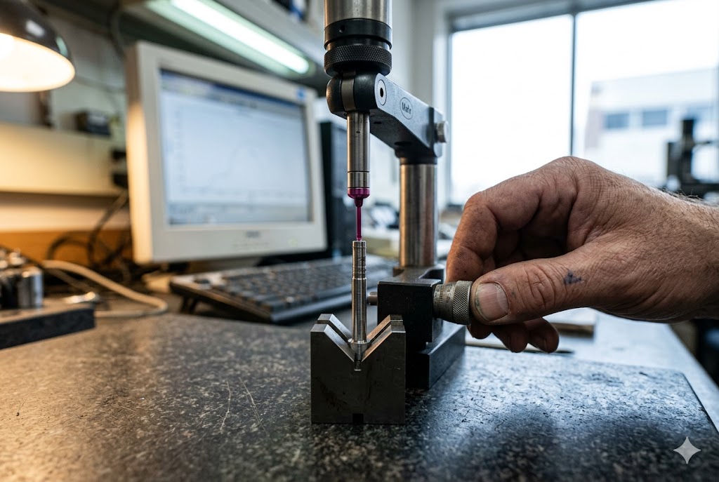
A factory verifying cylindricity on Swiss-turned parts should use a dedicated roundness/cylindricity measuring instrument (such as a Mahr MarForm 5) with rotational accuracy under 0.05 µm, not a standard CMM. CMMs lack the angular resolution to detect lobing patterns and chatter harmonics that are characteristic of Swiss-turning form error.

Why CMMs Miss the Problem
A coordinate measuring machine 6 samples discrete points on a surface and fits a geometric element to those points. The number of sample points is typically low — often 8 to 16 for a roundness check. A Swiss-turned part with three-lobe or five-lobe chatter error can pass a CMM roundness check at 8 points and still be visibly out of round under a roundness instrument that captures 3,600 points per revolution.
For cylindricity specifically, the CMM must also capture axis straightness and surface generator straightness along the full part length. On high L/D ratio Swiss-turned parts, this requires a carefully defined scanning strategy — most factory CMM operators do not use one.
Instrument Selection by Feature Size
| Part Feature | Recommended Instrument | Typical Measurement Points | Detects Lobing? |
|---|---|---|---|
| OD < 5 mm, tolerance < 0.010 mm | Roundness/cylindricity instrument (e.g., Mahr MarForm) | 3,600+ per revolution | Yes |
| OD 5–25 mm, tolerance 0.010–0.025 mm | Roundness instrument or high-resolution CMM with scanning probe | 360+ per revolution | Partially |
| OD > 25 mm, tolerance > 0.025 mm | Standard CMM with appropriate sampling | 16–32 points | No — but sufficient for tolerance |
The Reference Algorithm Problem
This is where conformance disputes start. The same physical part can report meaningfully different roundness values depending on which reference circle algorithm the measuring instrument applies:
- Minimum Zone (MZ): Required by ASME Y14.5 7 and ISO 1101 8. Finds the two concentric circles of minimum radial separation that contain the profile.
- Least Squares (LS): Statistical average circle. Reports a smaller error value than MZ for the same part. This is the default on most Chinese supplier CMM software.
- Maximum Inscribed / Minimum Circumscribed: Used for fit-based applications.
A part measured by a Chinese supplier using Least Squares can appear to conform to your drawing tolerance, then fail your incoming inspection using Minimum Zone evaluation 9 — even though both instruments are functioning correctly. This is not a calibration problem. It is a definition problem.
The fix is simple: specify the required reference circle algorithm directly on the drawing or in the quality plan. Add a note such as: "Roundness and cylindricity to be evaluated using Minimum Zone reference circle per ASME Y14.5 / ISO 1101." We add this clause to every quality plan we write for Swiss-turned parts with form tolerances tighter than 0.015 mm.
How Tight a Cylindricity Tolerance Can a Chinese Swiss CNC Factory Reliably Hold in Mass Production?
First-article results are easy to cherry-pick. The question that matters for sourcing is what the Cpk looks like at piece 8,000.
In mass production, a well-equipped Chinese Swiss CNC factory using centerless-ground bar stock, fixed guide bushings, and climate-controlled cutting fluid can reliably hold cylindricity to ±0.008 mm (Cpk ≥ 1.33 10) on parts under 10 mm in diameter. Tolerances tighter than ±0.005 mm are achievable but require dedicated process controls and are not sustainable across all materials.

Capability by Material
Material behavior is a major driver of form tolerance capability in Swiss turning. Work-hardening materials — austenitic stainless (303, 316), titanium alloys, and Inconel — generate chatter harmonics that appear as repeating, evenly-spaced peaks on a roundness trace. These are distinct from random form error. They require bushing tension adjustment to shift the structural resonance frequency, not just a change in cutting speed or feed.
| Material | Typical Mass-Production Cylindricity Floor | Key Challenge |
|---|---|---|
| 303 Stainless | ±0.008–0.012 mm | Work-hardening, built-up edge |
| 316L Stainless | ±0.010–0.015 mm | Higher work-hardening rate than 303 |
| Titanium (Ti-6Al-4V) | ±0.012–0.020 mm | Chatter harmonics, heat buildup |
| Brass (C360) | ±0.005–0.008 mm | Favorable — free-machining |
| Aluminum (6061-T6) | ±0.005–0.008 mm | Favorable — but requires rotary bushing trade-off |
| Inconel 718 | ±0.015–0.025 mm | Most difficult — rapid tool wear shifts form |
Bar Stock OD Variation: A Hidden Production Risk
Within a single bar lot, OD variation can exceed expectations. If bar OD variation exceeds ±0.076 mm within a standard bushing assembly, the bushing fit oscillates between too loose and too tight during the run. The result is alternating roundness conditions — and in severe cases, spindle servo overload from bushing seizure.
We specify incoming bar OD variation limits in our supplier quality agreements for all jobs with cylindricity callouts tighter than 0.015 mm. Most Chinese bar stock suppliers can meet h7 classification. Fewer can guarantee lot-to-lot consistency without incoming inspection data.
Sub-Spindle Transfer and Post-Release Distortion
For parts requiring back-working operations, the sub-spindle introduces a discrete form-error injection point. Grip pressure from the sub-spindle collet during back-working can elastically distort small-diameter, thin-walled features. This distortion relaxes after part release.
The practical implication: cylindricity measured at the machine will differ from cylindricity measured on a CMM after part ejection and thermal stabilization. For thin-walled parts, we require suppliers to specify dwell time and ambient temperature stabilization period before final inspection. This is a detail most buyers never ask for — and most factories never volunteer.
Should I Specify Roundness or Total Runout on My Drawing, and What Is the Practical Difference?
Buyers often use roundness and total runout interchangeably on drawings. Suppliers often let that ambiguity pass without comment. The result is tolerance callouts that mean different things to the buyer, the supplier, and the inspector.
Roundness (circularity) controls only the cross-sectional form of a single circular element — it says nothing about axis straightness or surface variation along the part length. Total runout controls both form and coaxiality of the entire surface relative to a datum axis. For rotating parts or bearing fits, total runout is almost always the correct callout; roundness alone is insufficient.

Definitions Side by Side
It helps to see these tolerances defined clearly before choosing between them.
| GD&T Symbol | Controls | Datum Required? | Measured By |
|---|---|---|---|
| Roundness (○) | Cross-sectional form only, single plane | No | Roundness instrument, single plane |
| Cylindricity (⌭) | Form + axis straightness + surface generator, full length | No | Cylindricity instrument, full length |
| Total Runout (↗↗) | Form + coaxiality relative to datum axis, full surface | Yes | Indicator swept along full surface while rotating on datum |
| Circular Runout (↗) | Form + coaxiality relative to datum axis, single cross-section | Yes | Indicator at single plane while rotating on datum |
When to Use Each Callout
Use roundness when the only concern is the shape of a single cross-section and the part does not rotate relative to another feature in service. This is rare for precision mechanical parts. It is common for sealing surfaces that contact in a single plane.
Use cylindricity when form must be controlled along the entire part length and no datum reference is needed. Cylindricity is harder to inspect and harder to hold. It compounds roundness, axis straightness, and surface generator straightness simultaneously. Use it only when all three genuinely matter.
Use total runout when the part will rotate on a bearing or mate with a bore. Total runout captures what the part will actually do in service. It requires a datum axis, which means the datum must be defined on the drawing and reproduced at inspection — both at the supplier and at incoming.
How Cylindricity Compounds the Challenge
Cylindricity callouts are the most demanding of the three. The Z-axis interpolation accuracy of the sliding headstock servo on a Swiss lathe directly contributes to cylindricity error in ways that single-plane roundness inspection will never detect. A part can pass a roundness check at any individual cross-section and still fail cylindricity because the axis is bent or the surface generator is tapered.
For high L/D ratio Swiss-turned parts — anything with length more than five times the diameter — we strongly recommend cylindricity inspection over roundness inspection when form along the full length matters. We also recommend including the required measurement algorithm (Minimum Zone per ISO 1101) in the quality plan, for the same reasons discussed in the measurement section above.
Practical Guidance for Drawing Callouts
When we review customer drawings before placing orders with Swiss CNC suppliers, we flag three common errors in form tolerance callouts:
- Roundness specified where total runout was intended — the supplier conforms to the easier callout.
- Cylindricity called out with no measurement protocol specified — the supplier inspects at a single cross-section and reports it as cylindricity.
- No reference circle algorithm specified — the supplier reports Least Squares values against a drawing that implies Minimum Zone.
None of these are fraud. They are gaps in the drawing and quality plan that cost money at incoming inspection. Closing them before the first production run is always cheaper than arguing about them afterward.
Conclusion
Roundness and cylindricity tolerances on Swiss CNC parts are controlled by a chain of variables — bar stock quality, bushing fit, thermal management, material behavior, and measurement protocol. Any break in that chain shows up in your incoming inspection data. Specifying the right callout, the right bar stock classification, the right bushing type, and the right measurement algorithm on your drawing and quality plan is the fastest way to prevent conformance disputes before production starts.
Footnotes
1. Overview of how Swiss-type CNC lathes work, including guide bushing mechanics and sliding headstock design. ↩︎
2. Precision centerless-ground bar stock specifications for close-tolerance machining applications. ↩︎
3. Detailed comparison of fixed vs. rotary guide bushings and their effect on Swiss lathe precision. ↩︎
4. Peer-reviewed study on spindle axial thermal growth modeling and compensation on CNC turning machines. ↩︎
5. Mahr MarForm precision form-measuring instruments for roundness and cylindricity per ISO 1101. ↩︎
6. Wikipedia overview of coordinate measuring machine capabilities, limitations, and GD&T applications. ↩︎
7. Wikipedia entry on ASME Y14.5, the authoritative U.S. standard for GD&T symbols and tolerancing rules. ↩︎
8. ISO 1101 standard overview covering geometric tolerancing symbols including cylindricity and roundness. ↩︎
9. PMC research article comparing Minimum Zone and Least Squares roundness evaluation methods per ASME/ISO. ↩︎
10. Explanation of the Cpk process capability index, including the Cpk ≥ 1.33 threshold for production acceptance. ↩︎



