 Skip to main content Skip to footer

We see it happen often on our production floor: a client sends a drawing with a blanket Ra 0.4 µm callout across every surface, and the quote comes back 35% higher than expected. The finish spec is doing damage before a single chip is cut.
Swiss-type CNC lathes can achieve a native as-machined surface finish of Ra 0.2–1.6 µm under optimized cutting conditions. This is finer than conventional CNC turning's typical Ra 0.8–3.2 µm range, made possible by the guide bushing support 1 that minimizes workpiece deflection during cutting.
Setting the right Ra standard is not just a technical choice. It is a cost and quality decision. Read on to understand exactly what is achievable, what it costs, and how to write specs that protect you without overpaying.
Can a Chinese Swiss CNC Factory Achieve Ra 0.4 µm or Better Without Secondary Polishing?
Our sourcing team visits Swiss-type screw machine shops in Guangdong and Zhejiang regularly. The honest answer surprises many buyers.
A Chinese Swiss CNC factory can achieve Ra 0.4 µm or better without secondary polishing, but only under specific conditions: free-machining brass or 6061-T6 aluminum, optimized tooling, low feed rate, and a skilled operator. For stainless steel or titanium alloys, Ra below 0.4 µm typically requires grinding or superfinishing.
What the Shop Floor Reality Looks Like
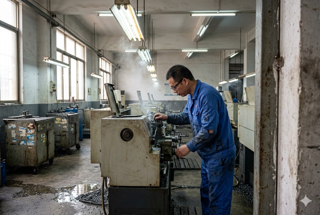
Most mid-tier Chinese Swiss-type shops run production at Ra 1.6–3.2 µm by default. This is their comfort zone. It is fast, tooling lasts longer, and customers rarely measure carefully enough to notice a difference on non-critical features.
Achieving Ra 0.4 µm on-machine is possible, but it requires deliberate setup. Here is what has to go right at the same time:
Material Is the First Gate
Material machinability places a hard ceiling on achievable Ra. No amount of feed adjustment can overcome a poor-machining material.
| Material | Practical Ra Floor (Swiss Turning) | Notes |
|---|---|---|
| Free-machining brass C36000 | Ra 0.2–0.4 µm | Most favorable, excellent chip break |
| 6061-T6 aluminum | Ra 0.2–0.4 µm | Requires sharp tooling, no BUE |
| 303 stainless steel | Ra 0.4–0.8 µm | Possible with excellent tooling; inconsistent |
| 316L stainless steel | Ra 0.8–1.6 µm | Work-hardening limits finish |
| 17-4 PH stainless (H900) | Ra 0.8–1.6 µm | Secondary finishing usually needed |
| Grade 5 titanium (Ti-6Al-4V) | Ra 0.8–1.6 µm | Cannot reliably achieve below 0.8 µm in turning |
If your part material sits in the lower rows of that table, write your drawing callout accordingly, or build in a grinding operation. Do not write Ra 0.4 µm on a titanium connector pin and expect a Swiss screw machine to deliver it.
What Happens When Spec and Reality Do Not Match
When a shop receives an Ra 0.4 µm callout it cannot meet in titanium, most will not tell you upfront. They will machine the part, measure with a comparator plate instead of a profilometer, sign it off, and ship. You receive non-conforming parts that pass a visual check but fail a profilometer trace. This is a quiet conformance risk that surfaces only at incoming inspection — or worse, at your customer.
The fix is simple: specify Ra in micrometers on drawings sent to Chinese suppliers. All Chinese shops work in SI units per GB/T standards. Microinch callouts (µin) are frequently misread or converted incorrectly. Write Ra 0.8 µm, not Ra 32 µin. It removes one silent failure mode before the order is placed.
Tooling and Setup Requirements for Fine Finish
To push toward Ra 0.4 µm on favorable materials, the shop needs:
- Insert grades rated for finishing, not roughing
- Tool nose radius of 0.4–0.8 mm minimum
- Feed rate below 0.05 mm/rev
- Spindle speed in the upper range for the material
- Clean, high-pressure coolant delivery
- No tool wear — inserts changed on schedule, not when they break
Ask your supplier whether they track tool change intervals in writing. A shop that cannot answer that question clearly is not set up to hold Ra 0.4 µm in production, only in samples.
Among favorable materials, free-machining brass C36000 2 with its 100% machinability rating is the most reliable choice when the finest as-machined finish is needed without secondary operations.
How Does Cutting Speed and Coolant Type Affect the Surface Roughness of My Turned Parts?
When our engineers review a supplier's process sheet and see no mention of coolant type or cutting speed targets, that is a red flag. These two variables together have more influence on final Ra than most buyers realize.
The three primary process levers for Ra on a Swiss lathe are feed rate (the most powerful single variable), cutting speed optimized for the workpiece material, and coolant delivery method. All three interact. Tuning one without the others yields diminishing returns and inconsistent results across a production batch.

Feed Rate: The Biggest Lever
Feed rate directly controls the theoretical peak-to-valley height left by each tool pass. The relationship is not linear — halving the feed rate more than halves the Ra value. This is why feed rate adjustment is always the first move when chasing a finer finish.
A practical rule: for every step down in finish requirement (for example, from Ra 1.6 µm to Ra 0.8 µm), expect feed rate to drop by roughly 40–50% and cycle time to increase accordingly. This is why blanket fine-finish callouts increase part cost so significantly.
Cutting Speed and Built-Up Edge
Cutting speed matters most at the low end of the range. When cutting speed is too low for the material, built-up edge (BUE) 3 forms on the tool tip. BUE creates random, unpredictable peaks on the machined surface. It is particularly destructive to Ra on aluminum and low-carbon steels. Increasing cutting speed past the BUE threshold improves surface finish significantly — often more than adjusting feed rate alone.
At very high cutting speeds, heat becomes the limiting factor. Tool wear accelerates, and finish degrades as the insert dulls.
| Cutting Speed Zone | Effect on Surface Finish | Risk |
|---|---|---|
| Too low | BUE forms; rough, inconsistent Ra | High scrap rate |
| Optimal range | Smooth chip flow; best Ra for feed setting | Low |
| Too high | Tool wear accelerates; Ra degrades mid-batch | Inconsistent lot quality |
Coolant Type and Delivery
Coolant does three jobs: it lubricates the cut zone, removes heat, and flushes chips away from the cutting edge. All three affect Ra.
Flood coolant is the default at most Chinese Swiss shops. It is acceptable for Ra 1.6 µm and above on most materials. For finer finishes on stainless steel, flood coolant often is not enough — chip recutting against the machined surface creates surface damage that a profilometer will catch.
High-pressure coolant (HPC) 4 at 70–150 bar directed precisely at the tool-chip interface breaks chips more cleanly and reduces heat at the cutting edge. Swiss lathes with HPC capability can hold Ra 0.4–0.8 µm on stainless steel with much greater consistency than flood alone.
Neat cutting oil rather than water-based emulsion improves lubricity on difficult materials like titanium and improves Ra by 15–25% in practice. It is less common in Chinese production shops, so it is worth asking explicitly whether the shop has this capability before approving a supplier for titanium work.
Dry machining is used for some aluminum alloys and certain plastics. Without chip recutting risk and with correct speed, Ra values can be excellent. However, it requires tight process control and is not universally better than wet cutting.
Tool Nose Radius: The Third Variable
A larger tool nose radius leaves a smoother theoretical surface at the same feed rate. Doubling the nose radius (for example, from 0.2 mm to 0.4 mm) can reduce Ra by up to 30% at the same feed. This is a low-cost adjustment — it requires only an insert change, not a process rewrite.
The trade-off: a larger nose radius increases radial cutting force, which can cause deflection on very small-diameter parts (under 3 mm). On Swiss-type lathes, the guide bushing 5 minimizes this risk, making larger nose radii more practical than on conventional lathes.
How Do I Measure and Verify Surface Roughness Ra on a Batch of Small-Diameter Swiss-Turned Parts?
Measurement is where surface finish specifications either hold or collapse. We have seen suppliers report Ra 0.4 µm on a comparator plate assessment — a method that is not valid for contractual acceptance on functional surfaces.
To measure Ra on small-diameter Swiss-turned parts, use a contact profilometer with a 2 µm stylus tip radius, specify the measurement cutoff wavelength (λc) on the drawing, and require a printed profilometer trace — not a single reported number — as part of your first article inspection package. Comparator plate visual assessment is not acceptable as sole verification for Ra requirements on functional surfaces.

Why Small-Diameter Parts Create Measurement Problems
Swiss-turned components are often small — diameters from 0.5 mm to 12 mm are typical. At these sizes, standard profilometer cutoff wavelength settings can produce misleading readings.
The default measurement cutoff (λc) per ISO 4288 6 is 0.8 mm. This setting is designed for typical machined surfaces with features in that spatial frequency range. On a part with a 1 mm diameter, the profilometer stylus traverses the curved surface geometry, not just the roughness texture. The measured Ra can include waviness or even part geometry, reporting a value that does not represent the actual surface texture the function depends on.
The fix: specify λc on the drawing for any feature below 5 mm diameter. For features below 1 mm diameter, a cutoff of 0.08 mm or 0.25 mm is usually appropriate, matching the scale of actual surface texture rather than part geometry.
What to Require in Your Inspection Documentation
| Inspection Method | Appropriate Use | Not Acceptable For |
|---|---|---|
| Contact profilometer with trace printout | All functional surface Ra acceptance | — |
| Surface roughness comparator plate | Production screening, operator feedback | Contractual Ra acceptance on functional surfaces |
| Optical profilometer (non-contact) | Soft materials, very fine finishes below Ra 0.1 µm | Standard production inspection |
| Visual / tactile assessment | In-process operator check only | Any formal acceptance |
Require a profilometer trace printout — not just the reported Ra number — for every feature with a functional surface finish callout in your first article inspection (FAI) package. A single reported number can be cherry-picked. A printed trace shows the full texture profile and is harder to falsify.
Per ASME B46.1 7, first article surface finish documentation should include the measurement location, stylus force, cutoff wavelength, and the name of the instrument used. Ask your Chinese suppliers whether their profilometer meets this standard. Many mid-tier shops own a profilometer but do not document measurements at this level of detail unless the customer explicitly requires it.
Sampling Plan for Production Batches
Do not accept a single measurement as proof of conformance for a batch. A reasonable sampling plan:
- First article / PPAP: 100% of critical surfaces on 3–5 parts, full trace printout required
- Production batches under 500 pieces: measure Ra on 5–10% of parts at minimum, at the same location and measurement conditions as the FAI
- Production batches over 500 pieces: statistically-based sampling per your QMS; at minimum, check first-off, mid-run, and last-off parts
If your supplier uses a comparator plate for production screening, this is acceptable as an in-process operator check. It is not acceptable as the sole formal evidence of conformance for your incoming inspection acceptance.
Contractually Excluding Comparator Plate as Sole Verification
Add a line to your purchase order or supplier quality requirements: "Surface roughness Ra acceptance for features with a drawing callout shall be verified by contact profilometer. Comparator plate (roughness sample block) assessment is not acceptable as sole verification method for Ra callout compliance."
This one sentence prevents the most common surface finish inspection shortcut at mid-tier Chinese screw machine shops.
What Ra Value Should I Specify for Medical Implant Contact Surfaces Versus Industrial Connector Pins?
This is the question where over-specification does the most damage. We regularly review drawings where every surface — including internal clearance features that never contact anything — carries a medical-grade Ra callout.
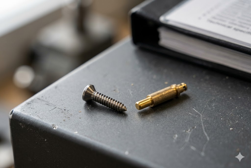
For medical implant contact surfaces, Ra 0.2–0.8 µm is the typical specification range, often with an Rz or Rpk callout added for sealing or osseointegration surfaces. For industrial connector pins, Ra 0.8–1.6 µm is usually sufficient for electrical contact and wear resistance. Applying medical-grade Ra callouts to industrial parts inflates machining cost 20–40% with no functional benefit.
Ra Is Not Always the Right Parameter
Ra is the arithmetic mean of surface height deviations 8 over the measurement length. It is useful, but it is a single-number summary that hides the shape of the texture. Two surfaces can have identical Ra values and behave completely differently in service.
For functional surfaces, consider whether Ra alone is the right call:
- Sealing surfaces (O-ring grooves, face seals): Ra alone does not capture peak heights that create leak paths. Specify Rz (maximum height) or Rpk (reduced peak height) in addition to Ra.
- Bearing journals and sliding interfaces: Rsk (skewness) tells you whether peaks or valleys dominate the texture. A negative Rsk (valley-dominated texture) reduces friction and wear in sliding contact. Ra does not capture this.
- Osseointegration surfaces on implants: some medical implant standards require a specific Rz range to promote bone cell adhesion, not just a fine Ra. Research into implant surface roughness and osseointegration 9 confirms that Ra alone is often insufficient to characterize surfaces for bone integration.
Recommended Ra by Application
| Application | Recommended Ra (µm) | Additional Parameters to Consider |
|---|---|---|
| Medical implant — bone contact | 0.8–2.0 µm (controlled texture) | Rz, surface chemistry, sterility |
| Medical implant — fluid contact (blood, tissue) | 0.2–0.4 µm | Rz, Rpk |
| Medical device — non-contact internal | 0.8–1.6 µm | None additional |
| Industrial connector pin — electrical contact | 0.8–1.6 µm | None additional for most applications |
| Hydraulic seal surface | 0.4–0.8 µm | Rz ≤ 4× Ra recommended |
| Bearing journal (rolling element) | 0.2–0.4 µm | Rsk negative preferred |
| Non-contact / clearance features | 1.6–3.2 µm (drawing general note) | None |
The Standard You Reference Matters
Drawing callouts must name the governing standard explicitly:
- ASME Y14.36M: used in US drawings; specific symbol conventions for lay, waviness, and roughness
- ISO 1302 10: used in international / metric drawings; different symbol assumptions
Omitting the standard leaves interpretation to the shop. A Chinese supplier working to GB/T defaults may read your finish symbol differently than you intended. Write the standard name on the drawing face — it takes five seconds and prevents a category of quiet non-conformance.
The Cost of Over-Specification
Applying a blanket fine-finish callout to every surface is the single most common over-specification error on Swiss-turned part drawings. A clearance hole, a relief groove, a non-contact shoulder — none of these need Ra 0.4 µm. But if the drawing says so, the supplier has to try to hold it, measure it, and document it, or they sign off on non-conformance.
The practical cost: adding an Ra 0.4 µm callout to surfaces that do not need it typically adds 20–40% to the machining quote. On high-volume Swiss-turned components, this compounds into significant annual overcharge for no functional return.
Audit your drawings. Apply fine-finish callouts only where function requires it. Set a drawing general note for all other surfaces — typically Ra 3.2 µm / 125 µin UOS (unless otherwise specified) — and let the shop optimize cycle time on non-critical features.
Conclusion
Swiss-type CNC lathes offer real surface finish capability — Ra 0.2–1.6 µm — but only when material, process parameters, measurement method, and drawing callouts are aligned. Specify Ra by function, reference the governing standard, and require profilometer trace documentation. That combination protects quality without overpaying.
Footnotes
1. Overview of Ra 0.2–1.6 µm achievable on Swiss-type lathes and the role of guide bushing support. ↩︎
2. C36000 free-machining brass properties, including its 100% machinability rating benchmark. ↩︎
3. Explanation of built-up edge formation, its effect on surface roughness, and suppression strategies. ↩︎
4. Peer-reviewed study on high-pressure coolant effects on surface finish in stainless steel turning. ↩︎
5. Technical guide to Swiss lathe guide bushings, history, and their contribution to finish and accuracy. ↩︎
6. Mahr guide to ISO 4288 cutoff wavelength selection for accurate surface roughness measurement. ↩︎
7. ANSI overview of ASME B46.1-2019 surface texture standard covering profilometer documentation. ↩︎
8. Explanation of Ra as arithmetic mean deviation and comparison with Rz for functional surfaces. ↩︎
9. NCBI study on Ti-6Al-4V superfinishing and the role of Rz in implant surface quality for osseointegration. ↩︎
10. ISO 1302:2002 standard governing surface texture indication in technical product documentation. ↩︎



