 Skip to main content Skip to footer

Thread rejections are expensive. We see it happen when buyers send drawings with vague tolerance callouts — the supplier picks a default grade, the parts arrive, and the mating assembly fails. Getting thread accuracy right starts at the drawing stage, not at incoming inspection.
Thread accuracy grades for Swiss CNC parts are selected by specifying a tolerance class — such as 6H for internal threads or 6g for external threads — under ISO 965. Verification uses Go/No-Go gauges for production runs and CMM or optical measurement for first articles and miniature threads below M3.
The sections below break down each part of this decision: what to specify, how to verify it, and what to watch for when ordering from a Chinese Swiss CNC supplier.
What Thread Tolerance Class Should You Specify for Precision-Fit Threaded Components?
Tolerance class errors are silent killers. A part can look perfect, pass visual checks, and still fail at assembly — because the pitch diameter drifted outside the mating envelope. We have seen this on plated fasteners more than anywhere else.
For general-purpose metric fastening threads, specify 6H for internal threads and 6g for external threads per ISO 965-2. For threads M1.4 and smaller — common on Swiss CNC parts — tighten to 5H/6h. For threads that will be plated, shift external threads to 6e or 6f before coating.
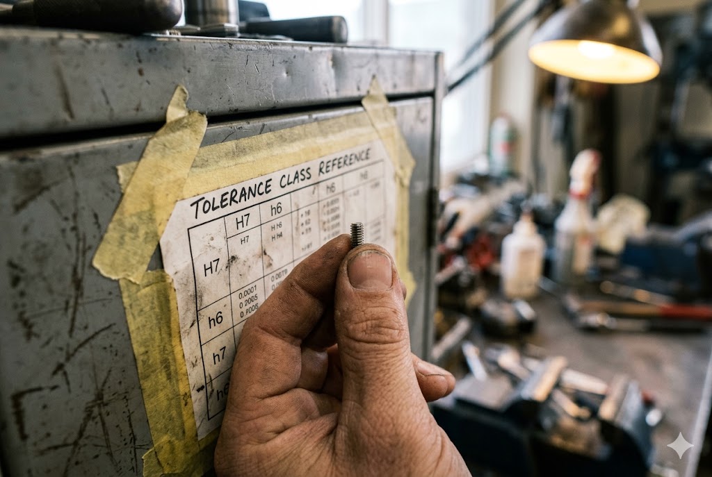
How ISO 965 Thread Tolerance Classes Work
Under ISO 965 1, a thread tolerance class is defined by two parameters: a tolerance grade and a tolerance position. The grade is a number — 4, 6, 8, and so on. A smaller number means a tighter tolerance band. The position is a letter. For internal threads, uppercase letters are used: H and G. For external threads, lowercase letters are used: g, h, e, f.
These two elements combine into a single designation. 6H means internal thread, grade 6, position H. 6g means external thread, grade 6, position g. When you see a callout like 6H/6g on a drawing, it describes the internal thread first and the external thread second.
| Thread Feature | Grade | Position | Designation | Application |
|---|---|---|---|---|
| Internal (nut) | 6 | H | 6H | General purpose metric threads |
| External (bolt) | 6 | g | 6g | General purpose metric threads |
| Internal (miniature) | 5 | H | 5H | Threads M1.4 and smaller |
| External (miniature) | 6 | h | 6h | Threads M1.4 and smaller |
| External (pre-plate) | 6 | e or f | 6e / 6f | Parts receiving electroplating |
Why Miniature Threads Require Tighter Grades
At small diameters, proportionally larger form errors occur. A pitch error that is acceptable on an M6 thread produces a disproportionate effect on an M1.2 thread. Swiss CNC machines are chosen precisely for small-diameter work, so this is not an edge case — it is the default condition on most Swiss-turned components.
Specify 5H/6h for anything M1.4 and below. If your drawing calls out 6H/6g on a miniature thread and the supplier follows it literally, you may receive parts that technically conform to the callout but fail to assemble with the mating component.
Coating Allowance Is Not Optional
Electroplating adds material. A zinc-nickel coating 2 at 8–12 microns builds the thread flank outward. If the thread was cut to a 6g tolerance, the coated thread will exceed the 6H mating envelope. The part will not assemble.
The fix is to cut the external thread to a tighter position — 6e or 6f — so that after plating, the effective pitch diameter lands within the 6g envelope. This must be stated explicitly on the drawing or in the PO notes. Do not assume the supplier will calculate it independently.
| Coating Type | Typical Buildup (per side) | Pre-Plate Tolerance | Post-Plate Target |
|---|---|---|---|
| Zinc-nickel | 8–12 µm | 6e | 6g |
| Hard chrome | 12–25 µm | 6e or 6f | 6g |
| Electroless nickel | 15–25 µm | 6e | 6g |
| Anodize (aluminum) | 5–25 µm | 6e | 6g |
Add a note to the drawing: External thread pre-plate tolerance 6e per ISO 965. Finished coated thread shall conform to 6g.
ISO 965 vs. GB/T 197: Do Not Assume Equivalence
Chinese suppliers may reference GB/T 197 3, the Chinese national thread standard. The grade numbering looks identical to ISO 965. It is not identical. At fine pitches and tight grades — 4H, 5H — the fundamental deviations and engagement-length groupings diverge enough to produce a non-interchangeable part.
State on your drawing: Thread tolerance per ISO 965. GB/T 197 substitution is not permitted. This one line eliminates a common source of first-article surprises when sourcing from Chinese factories.
How Does a Factory Verify Thread Accuracy — Go/No-Go Gauges Versus CMM Thread Measurement?
A supplier can produce threads correctly and still ship bad parts — if the verification method does not match the thread size or application. We require factories to define their gauging plan before first article. The measurement method matters as much as the tolerance callout.
Go/No-Go thread gauges per ISO 1502 are the primary production-floor verification method for thread tolerance class conformance. For sub-M3 threads, optical measurement systems or vision CMM routines replace gauges. CMM measurement is required at first article regardless of part size to verify thread form, not just pitch diameter.

How Go/No-Go Gauges Work in Practice
A Go/No-Go gauge 4 checks the pitch diameter at maximum material condition. The Go gauge must fully engage the thread. If it does not, the pitch diameter is too large (external) or too small (internal), and the part fails.
A No-Go gauge checks the minimum material limit. It should not engage beyond approximately two turns. If it does, the pitch diameter has exceeded the minimum material limit and the part also fails.
This two-gauge system confirms that the pitch diameter sits within the tolerance zone — not too large, not too small. It does not verify thread form, flank angle, or root geometry. That is an important limitation.
Ring gauges are used for external threads. Plug gauges are used for internal threads.
| Gauge Type | Thread Feature | Checks | Failure Condition |
|---|---|---|---|
| Go ring gauge | External | Pitch diameter at MMC | Gauge does not fully pass |
| No-Go ring gauge | External | Pitch diameter at LMC | Gauge engages beyond 2 turns |
| Go plug gauge | Internal | Pitch diameter at MMC | Gauge does not fully engage |
| No-Go plug gauge | Internal | Pitch diameter at LMC | Gauge engages beyond 2 turns |
Pitch Diameter Is the Critical Dimension
Major and minor diameters define clearance. Pitch diameter controls load-bearing flank contact, interchangeability, and the effective fit class. All gauge systems trace back to pitch diameter control. When a thread fails functionally under load or strips at an unexpected torque, pitch diameter is the first value to audit in the inspection records.
Gauge Calibration Is a Contractual Requirement, Not an Assumption
Go/No-Go gauges wear. A worn Go gauge accepts threads that should be rejected. Production can run for weeks, passing every gauge check, while the parts are systematically out of tolerance. This scenario is common — and preventable.
Gauges used in production must be calibrated against master thread gauges traceable to NIST 5 or an equivalent national standard. Calibration intervals must be defined in the supplier quality plan. Specify this in your PO or quality agreement: Thread gauges used for production inspection shall be calibrated per a documented schedule traceable to national standards. Calibration records shall be available upon request.
Sub-M3 Threads: When Gauges Stop Working
Below M3, conventional thread micrometers lose accuracy. Three-wire measurement becomes physically impractical. The wire diameter becomes too small to handle reliably, and measurement uncertainty exceeds the tolerance band.
For sub-M3 threads, video-based optical measurement systems or high-magnification vision CMM routines 6 are the only metrologically sound options for pitch diameter characterization. Ask the supplier directly: how do you measure pitch diameter on M1.6 threads? If the answer is "thread micrometers," that is a red flag.
In-Process Sampling Catches Thermal Drift
Long production runs on Swiss CNC machines generate heat. Thermal growth in the spindle and guide bushing causes gradual pitch diameter drift on external threads. First-article gauging alone does not capture this — it only confirms the first part.
Require in-process statistical sampling: every Nth part gauged, with data logged against cycle count. This creates a drift trend record. If pitch diameter is drifting toward the tolerance limit, the operator can make a correction before bad parts are produced.
Can Swiss-Type Lathes Thread-Mill and Single-Point Thread in the Same Setup?
Setup efficiency is a real cost driver. When a part requires multiple thread features — some internal, some external, some at different pitches — the question of what the machine can do in a single setup changes the quote and the lead time significantly.
Swiss-type lathes with live tooling can perform both single-point threading and thread milling in the same setup. Single-point threading uses the main spindle and a fixed tool. Thread milling uses a live rotary tool on the C-axis. Both methods run within the same program without rechucking.

Single-Point Threading on a Swiss Lathe
Single-point threading is the standard method for external threads on a Swiss lathe. The spindle rotates at a controlled speed. A threading insert advances along the Z-axis at a feed rate equal to the thread pitch. Multiple passes cut the thread progressively to final depth.
This method is fast and accurate. It works well for standard external threads — M2 through M20, UNC, UNF. The tool path is predictable, tool changes are minimal, and the setup is straightforward.
Internal single-point threading is also possible on Swiss machines, but access is limited for small bores. Below about M3 internal, boring bar rigidity becomes a constraint.
Thread Milling With Live Tooling
Thread milling 7 uses a rotating cutter on a live tool station. The cutter moves in a helical path around the thread feature. One full helix pass cuts a complete thread.
Thread milling offers several advantages over single-point threading for specific applications:
- It can cut both right-hand and left-hand threads with the same cutter by reversing the helix direction.
- It works well for threads close to a shoulder or at the bottom of a blind hole, where a tap could not retract without damaging the thread.
- Thread mills produce better chip evacuation in deep blind holes than taps.
- If the cutter breaks, it does not jam in the bore the way a broken tap does.
The tradeoff is cycle time. Thread milling is slower than tapping for high-volume production of standard thread sizes.
Comparing the Two Methods
| Parameter | Single-Point Threading | Thread Milling | Tapping |
|---|---|---|---|
| Setup complexity | Low | Medium | Low |
| Cycle time | Fast | Slow | Fastest |
| Internal thread access | Limited at small diameters | Good | Good (down to M1) |
| Left-hand threads | Requires separate tool | Same cutter | Separate tap required |
| Broken tool recovery | Easy | Easy | Difficult |
| Accuracy | High | High | Medium |
| Typical use case | External threads, standard pitches | Complex internal, blind holes | High-volume small threads |
What to Confirm With Your Supplier
Not all Swiss CNC machines have live tooling capable of thread milling. Some older or simpler Swiss configurations have limited or no C-axis capability. When quoting a part with mixed threading requirements, ask: Does your machine have live tooling with C-axis interpolation? Can you thread-mill and single-point thread in the same setup?
A capable supplier will answer this clearly and specify which method they plan to use for each thread feature on the drawing. If they cannot, that is a sign of limited process transparency.
What Thread Standards Do Chinese Factories Most Commonly Support?
Standard support varies more than buyers expect. A factory that confidently quotes ISO metric threads may struggle with UNF or have no experience with UNJF. Knowing the landscape helps you ask the right questions before committing to a supplier.
Chinese Swiss CNC factories most commonly support ISO metric threads (ISO 965 / GB/T 197) and are generally capable with UNC and UNF inch threads. Less common standards — such as UNJF, BSP, NPT, or MJ threads — require explicit confirmation of tooling availability and gauging capability before order placement.

ISO Metric Threads: The Default Standard in China
ISO metric threads are the domestic standard in China. Every Swiss CNC supplier works with them daily. Machine controllers are programmed in metric. Thread inserts and taps are stocked in metric sizes. Go/No-Go gauges are calibrated to metric thread classes.
This is your lowest-risk option when sourcing from Chinese factories. Even so, the GB/T 197 vs. ISO 965 equivalence problem noted earlier still applies. State ISO 965 primacy explicitly on the drawing.
UNC and UNF: Common but Verify Gauging
Most mid-sized Chinese Swiss CNC shops have experience with UNC and UNF inch threads 8. These are required for export work — particularly for the US market — so established suppliers have the tooling and gauges.
The risk is in gauging. Confirm that the supplier has calibrated inch-series Go/No-Go gauges in the specific sizes required. A supplier may have tooling to cut UNF threads but rely on optical measurement only for inspection, which introduces uncertainty compared to certified gauge-based verification.
Less Common Standards: Always Confirm
| Thread Standard | Common in China? | Risk Level | Recommended Action |
|---|---|---|---|
| ISO metric (M) | Very common | Low | State ISO 965, not GB/T 197 |
| UNC / UNF | Common | Low–Medium | Confirm gauge availability |
| UNJF (controlled root radius) | Uncommon | High | Require CMM thread profile verification |
| BSP (British Standard Pipe) | Limited | Medium | Confirm tooling and gauges |
| NPT (American National Pipe Taper) | Limited | Medium | Confirm tooling and thread form verification |
| MJ (aerospace metric) | Rare | High | Require first-article CMM report |
| ACME / trapezoidal | Some shops | Medium | Confirm insert geometry stock |
Thread Form Verification at First Article
Go/No-Go gauges confirm that pitch diameter is within the tolerance zone. They do not confirm thread form — flank angle, root radius, crest flatness. A thread that passes gauge inspection can still fail under cyclic load or vibration if the flank geometry is incorrect. Incorrect flank angles concentrate stress at the root.
For first articles, require an optical comparator overlay 9 against the nominal thread form chart, or a CMM flank-angle measurement. This applies regardless of which thread standard is being used. It is especially important for UNJF and MJ threads, where the controlled root radius is a functional requirement, not just a geometry preference.
For NPT taper pipe threads 10, thread form verification is particularly critical because the tapered geometry means standard Go/No-Go gauging principles change — the taper itself is a functional sealing parameter that must be independently confirmed.
State this on your first-article inspection requirements: Thread form shall be verified by optical comparator overlay or CMM flank-angle measurement at first article and after any tooling change.
Conclusion
Thread accuracy on Swiss CNC parts comes down to three things: specifying the correct tolerance class on the drawing, requiring the right verification method for the thread size, and confirming that your supplier has the tooling and gauges to support it. Address all three before the first order, and most downstream assembly failures become avoidable.
Footnotes
1. ISO 965 defines the tolerance system for general-purpose metric screw threads, including grade and position designations. ↩︎
2. Practical guidance on pre-plate pitch diameter allowances for zinc-plated threaded parts. ↩︎
3. GB/T 197-2018, the Chinese national standard for metric thread tolerances, is a modified adoption of ISO 965-1. ↩︎
4. Wikipedia overview of Go/No-Go gauges and their role in attribute-based thread inspection. ↩︎
5. Explains NIST traceable calibration and why an unbroken chain to national standards is required for measurement integrity. ↩︎
6. Best practices for measuring thread pitch diameter, flank angle, and form on coordinate measuring machines. ↩︎
7. Overview of Swiss CNC turning capabilities including live tooling, C-axis interpolation, and thread milling in a single setup. ↩︎
8. ASME B1.1-2024 covers thread form, series, class, and tolerance for UNC and UNF unified inch screw threads. ↩︎
9. Quality Magazine article on using optical comparators with overlay charts to inspect thread flank angle, minor diameter, and root radius. ↩︎
10. Wikipedia reference for NPT taper pipe thread standards, geometry, and sealing characteristics under ASME B1.20.1. ↩︎



