 Skip to main content Skip to footer
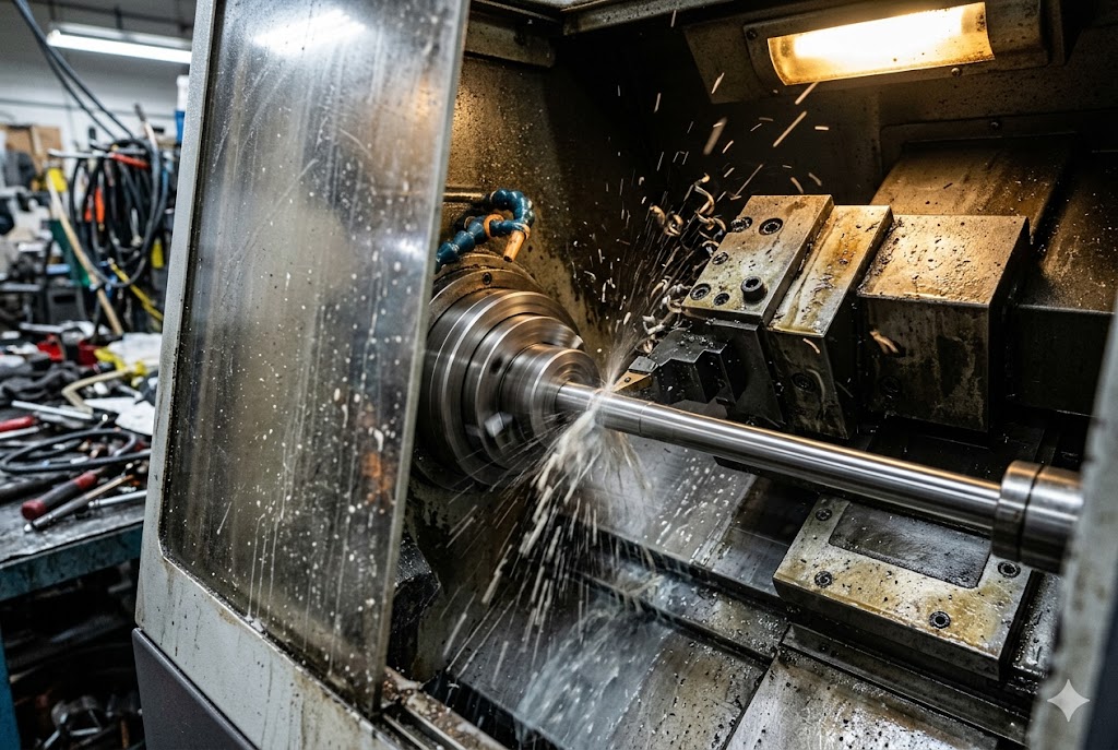
On our shop floor, slender shafts whip, bow, and chatter the moment a tool bites into them. A batch that comes back tapered or bent costs everyone time and money.
You prevent deflection in long slender shafts by using a guide bushing that supports the bar close to the cutting point, capping spindle speed instead of letting it rise with diameter, choosing straight pre-ground bar stock, and adding thermal control steps so parts hold their shape after cooling.
Let's break down each part of this process, starting with the guide bushing itself.
Why Is the Guide Bushing Critical for Preventing Deflection on Slender Swiss-Turned Shafts?
In our production cell, the guide bushing is the part everyone watches first. Get this wrong, and every other fix downstream stops mattering.
The guide bushing matters because it supports the bar stock within millimeters of the cutting tool, reducing the unsupported length to nearly zero. This lets Swiss machines hold L/D ratios above 10:1, where conventional lathes already struggle past 4:1.
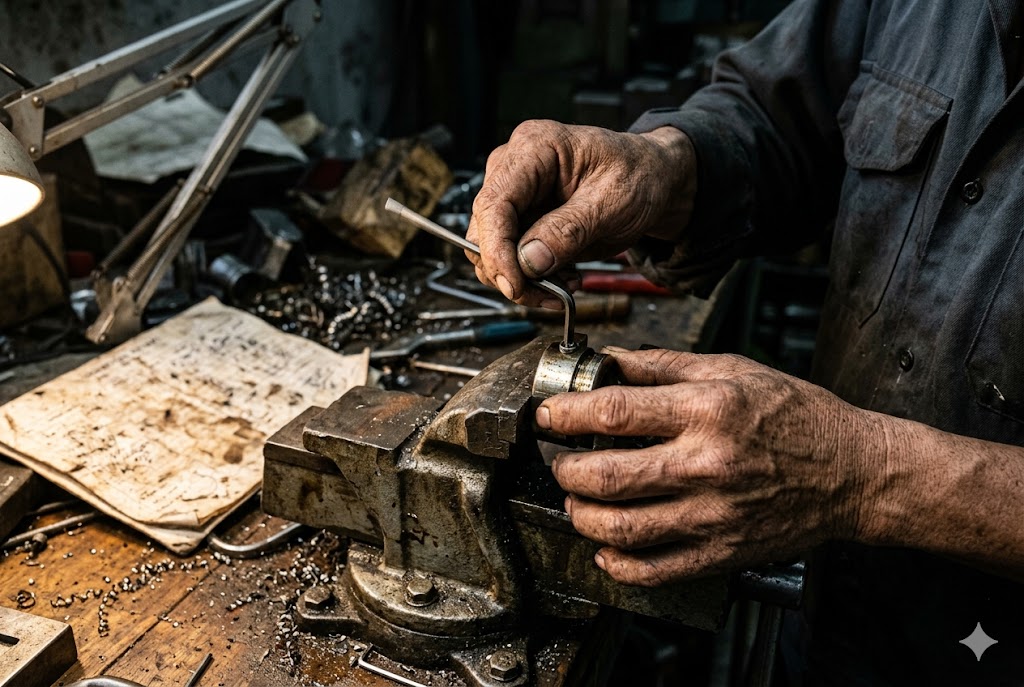
A guide bushing does one simple job. It holds the bar steady right where the cutting tool meets the metal. Without it, the bar flexes away from the tool as soon as the cut starts, and the finished part comes out tapered, oval, or visibly bent. With a properly set guide bushing, the unsupported length of bar drops to almost nothing, no matter how long the finished shaft turns out to be.
This is the reason Swiss-type lathes 1 can turn parts that other machines cannot touch. A standard CNC lathe usually needs a steady rest or a tailstock to manage anything past a 4:1 length-to-diameter ratio. A Swiss machine with a properly fitted guide bushing pushes that limit well past 10:1, and often much higher, because the support point travels with the cut instead of staying fixed at one end of the part.
Bushing clearance is the detail that separates a clean part from a scrapped one. Too much clearance lets the bar wobble inside the bushing, which brings back the same deflection problem the bushing is supposed to solve. Too little clearance creates friction, and that friction builds heat fast enough to warp a thin part before it ever leaves the spindle. We aim for clearance within a few ten-thousandths of an inch of the bar diameter, never more.
Fixed vs Rotating Guide Bushings
| Bushing Type | Best Bar Condition | Friction & Heat | Typical Use Case |
|---|---|---|---|
| Fixed carbide-lined | Centerless-ground bar | Higher friction, more heat | Tight-tolerance steel and stainless shafts |
| Rotating (live) | Non-ground or soft bar | Lower friction, less heat | Free-machining aluminum, sticky alloys |
Fixed carbide-lined bushings give the most rigid support and work best with ground bar stock that already runs true. Rotating bushings spin together with the bar, which cuts down friction and heat when the stock is not ground, or when the material is soft and sticky, like free-machining aluminum. Picking the wrong bushing type for the bar condition is one of the most common reasons a shop sees diameter drift or a slight bow appear partway through a long production run.
We check bushing wear and clearance on a fixed schedule, not just when a part starts to drift out of tolerance. By the time a part fails inspection, the run has often already produced scrap.
What L/D Ratio Threshold Requires Special Fixturing or Process Adjustments in Swiss Machining?
Our planners flag any job once the length-to-diameter math crosses a certain line. Past that point, normal settings just don't hold up.
An L/D ratio above 10:1 is the general threshold where Swiss machining needs extra care, such as tighter bushing clearance, spindle speed variation, or staged cutting sequences. Past 20:1, most jobs require pre-ground bar stock and slower finishing passes to stay in tolerance.
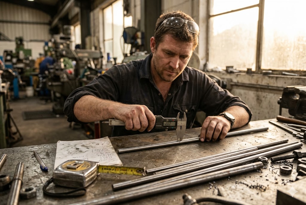
Length-to-diameter ratio is simple math, but it decides how a slender shaft behaves once metal starts coming off. Take the unsupported working length of the part and divide it by the diameter. The higher that number climbs, the more the thin section wants to bow, whip, or chatter under the cutting force.
Most shops treat 4:1 as the point where a standard lathe needs extra support, like a steady rest. Swiss machines move past that limit easily because the guide bushing travels close to the cut, but Swiss jobs still hit their own step points as the ratio keeps climbing.
Where the Risk Steps Up
| L/D Ratio | Typical Risk Level | Process Adjustment Needed |
|---|---|---|
| Below 6:1 | Low | Standard guide bushing setup |
| 6:1 to 10:1 | Moderate | Tighter bushing clearance, capped RPM |
| 10:1 to 20:1 | High | Spindle speed variation, staged cuts |
| Above 20:1 | Very high | Pre-ground bar, CAM taper compensation |
Past a 10:1 ratio, we tighten bushing clearance and cap spindle speed so it never climbs with constant surface speed as the diameter shrinks. Letting RPM rise uncapped on a thin diameter can drive the part through its natural frequency, and that produces the kind of harmonic whipping that ruins a finish pass. Spindle speed variation 2 programming helps here too, since it keeps shifting the RPM within a set range so the cut never locks into one resonant frequency.
Past a 20:1 ratio, bar quality starts to matter as much as the machine settings. Centerless-ground bar 3 holds straighter than standard cold-drawn stock, and CAM-level taper compensation can correct for the small amount of springback that even a well-set bushing cannot fully remove. We also sequence operations from the bushing face rearward, so a long, thin, unsupported neck is never left hanging out in front of the cutter while a remote feature gets machined.
Knowing where your part sits on this scale before the program is written saves a lot of scrapped bar further down the line.
How Does Workpiece Material Stiffness Affect Deflection Risk During High-Speed Swiss Turning?
Our engineers treat material choice as a deflection variable, not just a strength spec. Stiff stock and bendy stock behave very differently under the same cutting parameters.
Stiffer materials like steel resist deflection better than soft, ductile metals such as brass or aluminum, which bend more easily under cutting force. However, soft materials generate less heat, so the real risk shifts from mechanical bending to thermal expansion and post-machining warpage as the part cools.
Material stiffness changes how a slender shaft responds to the same cutting parameters, and it is easy to underestimate this until a batch comes back out of tolerance. A stiff material like carbon steel resists bending under cutting force, so it holds its shape even at higher L/D ratios. A soft, ductile material like brass or aluminum bends more easily under the same force, even though it cuts faster and generates less heat at the tool.
Material Stiffness and Deflection Risk
| Material | Stiffness | Main Deflection Risk | Recommended Control |
|---|---|---|---|
| Carbon steel | High | Mechanical bending at high L/D | Standard bushing clearance |
| Stainless (303, 17-4) | Medium | Residual stress warpage | Stress-relieved or annealed bar |
| Brass | Low | Thermal expansion after cooling | Cooling dwell before final pass |
| Aluminum | Low | Heat-induced bow, galling | Rotating bushing, flood coolant |
| Titanium | Medium | Unpredictable residual stress | Annealed bar, slower passes |
Why Spindle Speed Caps Matter More for Thin Stock
As a slender shaft gets thinner during turning, constant surface speed programming naturally wants to push RPM higher to keep cutting speed constant. On a soft, low-stiffness material this is risky, because the thin, flexible end of the part can pass through a natural frequency and start to whip. We cap RPM at a fixed ceiling rather than letting it float upward, which costs a little cycle time but keeps the part stable through the final passes.
Thermal Expansion Is a Separate Problem
Heat is its own deflection mode, and it shows up after the cut, not during it. Brass and aluminum expand more than steel 4 for the same temperature rise, so a part can measure in spec right off the machine and then shrink out of tolerance once it cools. High-volume flood coolant and a short cooling dwell before the final finishing pass solve this without touching the mechanical setup at all.
Cold-drawn bar also carries locked-in stress from the drawing process, and that stress does not show up until material is removed and the part is free to move. Stainless grades like 303 and 17-4 5, along with titanium alloys, are especially unpredictable here. Specifying stress-relieved or annealed bar removes this risk before the part ever reaches the spindle.
Can I Request a Sample of a Long Slender Part Before Committing to Full Production Volume?
We get this question on almost every new slender-shaft inquiry. Buyers want proof a process works before thousands of parts are on the line.
Yes, you can request a sample run before full production. A small batch, usually 5 to 20 pieces, lets you check straightness, surface finish, and dimensional tolerance on the actual bushing and tooling setup before committing to thousands of parts.

Requesting a sample before full production is standard practice for slender shaft parts, and we encourage every new client to do it. A small batch lets everyone see how the actual bushing setup, bar stock, and tooling perform together, instead of relying on a quote and a drawing alone.
What a Sample Run Should Include
A useful sample is not just one part pulled off the line. It should come from the same bar stock, same bushing clearance, and same spindle program planned for the full order. Anything less tells you little about how the real production run will behave.
| Check Point | Why It Matters | Tool Used |
|---|---|---|
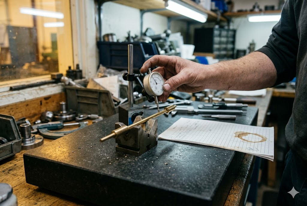
| Straightness / TIR | Confirms bar quality and bushing setup hold the part true | Dial indicator, V-block |
| Surface finish | Reveals chatter or thermal damage on the thinnest sections | Surface comparator |
| Dimensional tolerance | Confirms the process holds spec across the full length | CMM or micrometer |
| Post-cooling dimension | Catches thermal expansion in brass or aluminum parts | Re-measure after 24 hours |
Reading the Sample Before You Approve Full Production
Straightness is the first thing to check, since a bent or tapered sample points straight back to bushing clearance or bar quality. Surface finish on the thinnest section of the shaft often shows chatter marks before a dial indicator catches anything, so a visual check under good light matters. Dimensional checks using a CMM 6 should happen twice, once right after machining and again after the part sits for a day, because thermal expansion in brass or aluminum can hide a problem that only appears once the part cools fully.
For buyers managing downstream production schedules, a sample run also protects against the costs that matter most: late delivery, dimensional failures, and the back-and-forth of unprofessional technical answers from a sales contact who has never run a lathe. A sample turns those risks into something you can measure and approve before committing to volume, rather than discovering them in a container that has already shipped.
If your slender shaft project is still in the design stage, our Rapid Prototyping Service can turn your drawing into a test piece within days — so you can validate geometry and tolerance before tooling for production.
Swiss machining tolerances 7 as tight as ±0.0002 inches are achievable when the bushing setup and bar stock are correct, making the sample run the most reliable way to confirm that your specific geometry will hold through a full production order.
For parts with very high L/D ratios, stress relief heat treatment 8 on the bar stock before machining is worth specifying in the sample requirement, since cold-drawn bar can release internal stress and bow the part once material is removed.
A programmable guide bushing 9 system allows pressure adjustments based on dynamic conditions during the run, which is especially useful when validating a new slender shaft design across the first sample batch.
Finally, for titanium or high-alloy parts 10, the sample inspection plan should include a post-cooling dimensional check, since residual stress release in these materials is harder to predict than in standard steel or aluminum.
Conclusion
Slender shafts don't have to bend or drift out of spec. With the right bushing, bar stock, and process controls, you can hold a straight part every time.
Footnotes
1. How Swiss-type turning supports slender parts at L/D ratios a conventional lathe cannot reach. ↩︎
2. How spindle speed variation (SSV) prevents chatter lock on thin CNC-turned sections. ↩︎
3. Why centerless-ground bar holds tighter straightness than standard cold-drawn stock. ↩︎
4. Coefficient of thermal expansion data showing why aluminum and brass drift after machining. ↩︎
5. Stress-relief treatment options for austenitic stainless steel to maintain dimensional stability. ↩︎
6. How CMM inspection captures three-dimensional part geometry for precision quality control. ↩︎
7. Swiss machining tolerance capabilities versus conventional CNC turning and milling. ↩︎
8. What stress relief heat treatment is and why it reduces post-machining distortion. ↩︎
9. How programmable guide bushing pressure adapts to bar stock variance during Swiss turning. ↩︎
10. Why Swiss machining is the preferred platform for long, slender titanium and alloy parts. ↩︎



