 Skip to main content Skip to footer
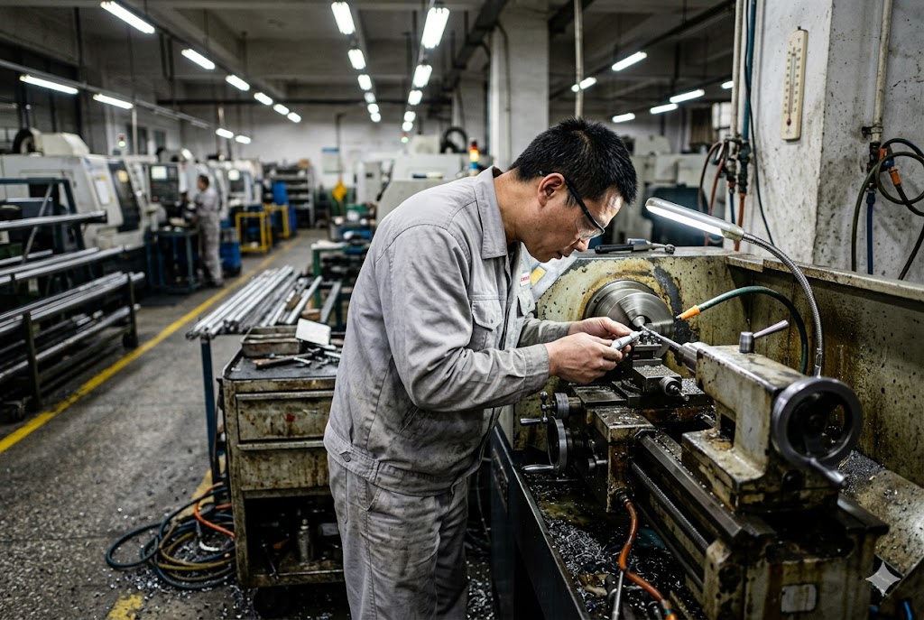
We've seen it happen more than once on our production floor: a batch of Swiss-turned parts passes first-article inspection in the morning, then fails the customer's incoming CMM check in the afternoon. No change in program, no change in tooling. Just temperature — and no one accounted for it.
Thermal expansion causes dimensional drift in Swiss CNC parts when ambient temperature, coolant temperature, and machine warm-up time are not controlled. Even a 1–2°C shift can push a ±0.005 mm tolerance out of spec. Material CTE, inspection temperature, and machine thermal state all contribute to the final dimensional outcome.
If you're sourcing tight-tolerance Swiss-turned parts from China, thermal management is not a detail. It's a process requirement — and it belongs in your purchase order.
How Should I Account for CTE Differences Between Materials When Setting Tolerances on Mating Parts?
Dissimilar materials expand at different rates. When we machine a brass insert designed to press-fit into a steel housing, we don't just look at the room-temperature dimensions. We calculate what happens at the assembly's operating temperature — because that's where the fit actually matters.
CTE mismatch between mating Swiss-turned parts must be evaluated across the full operating temperature range, not just at 20°C. An interference fit that is dimensionally correct at room temperature can relax to a clearance fit — or crack the housing — at elevated service temperatures if the CTE differential is not explicitly specified on the drawing.

What Is CTE and Why Does It Matter?
The coefficient of thermal expansion (CTE) describes how much a material expands per unit length per degree of temperature change. It is typically expressed in µm/m·°C or ppm/°C. For Swiss-turned parts 1, even small CTE differences between mating components create dimensional changes at the interface when temperature shifts.
Aluminum expands roughly three times faster than steel. A brass insert in a steel bore behaves differently than a steel pin in a steel bore. At room temperature, your fits may look fine. At 80°C operating temperature, the aluminum component has grown significantly more than the steel housing. The fit class you specified may no longer exist.
CTE Reference Table for Common Swiss-Turned Materials
| Material | CTE (µm/m·°C) | Common Use Case |
|---|---|---|
| 6061 Aluminum | ~23 | Lightweight housings, brackets |
| C360 Brass | ~19 | Inserts, fittings, connectors |
| 303 Stainless Steel | ~17 | Medical, food-grade shafts |
| 416 Stainless Steel | ~10 | Valve stems, high-strength parts |
| 17-4 PH Stainless | ~10.8 | Aerospace fasteners |
| Low-carbon Steel (1018) | ~12 | General-purpose structural parts |
| Titanium Grade 5 | ~8.6 | High-performance aerospace parts |
How to Specify CTE-Aware Fit Classes on Your Drawing
Your drawing note should not just specify the fit class (H7/p6, for example). It should also state the temperature at which that fit is defined. If the assembly operates between 20°C and 120°C, the fit class must remain valid across that range. This requires calculating the dimensional change for each mating component separately using the published thermal expansion coefficients for each material 2:
ΔL = L × CTE × ΔT
Where L is the nominal dimension, CTE is the material's coefficient, and ΔT is the temperature change from the reference condition.
For a 25 mm aluminum insert in a steel housing, operating at 100°C above room temperature:
- Aluminum growth: 25 × 23 × 100 = 57,500 µm/m → 0.0575 mm on a 25 mm diameter
- Steel growth: 25 × 12 × 100 = 30,000 µm/m → 0.030 mm on a 25 mm diameter
- Net differential: 0.0275 mm — enough to completely destroy a ±0.010 mm fit tolerance
This calculation belongs on the drawing or in the engineering notes. If you leave it out, the supplier will machine to room-temperature dimensions and assume your fit class holds across all temperatures. It will not.
What to Add to Your PO or Drawing
Add a note specifying: "Fit class [X] is defined at 20°C per ISO 1. Supplier shall verify dimensional compatibility at [minimum operating temp] and [maximum operating temp] using provided CTE values. CTE mismatch analysis shall be submitted with PPAP documentation." 3
Do Chinese Swiss CNC Factories Control Workshop Temperature to Minimize Thermal Dimensional Variation?
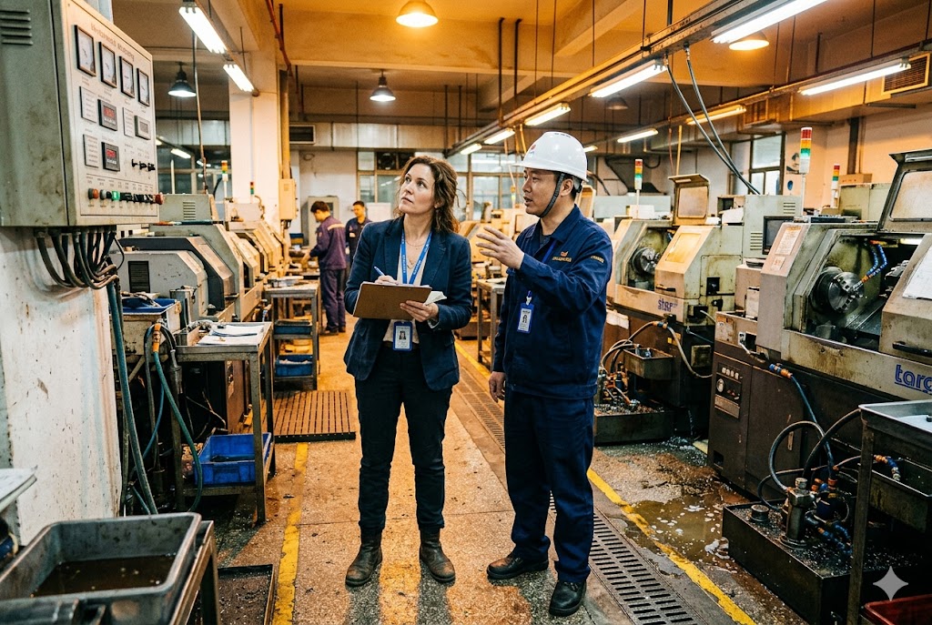
This is one of the first questions we encourage buyers to ask during a factory audit. Not every shop in China controls workshop temperature — and the difference matters enormously when you're holding ±0.005 mm or tighter.
Chinese Swiss CNC factories vary widely in thermal control capability. High-tier precision shops maintain workshop temperature at 20°C ±1°C with HVAC and temperature logging. Mid-tier shops may control temperature to ±3–5°C. Budget shops often run at ambient temperature, which in southern China can reach 28–35°C in summer, introducing systematic dimensional bias in all production parts.
Machine Warm-Up Is Not Optional
Spindles, bearings, guide bushings, and machine castings all expand during the first 30 to 90 minutes of operation. Parts produced during machine warm-up will systematically differ from parts produced after thermal equilibrium is reached — even with identical CNC offsets. A responsible factory runs a warm-up cycle before cutting production parts and does not include early-run pieces in the production lot without re-inspection.
Ask your supplier: "What is your machine warm-up procedure before production?" If they don't have a documented answer, that tells you something important.
Coolant Temperature Stability
Coolant is a primary thermal control mechanism, not a secondary one. Uncontrolled coolant acts as a variable heat source. As the coolant tank warms through the shift, the effective cutting temperature rises, and workpiece and machine temperatures drift with it.
Higher-tier shops use temperature-controlled chiller units to maintain coolant at a consistent delivery temperature — typically 20°C ±1°C. This suppresses both workpiece heat buildup and machine structure drift across the full production shift.
Factory Tier Classification by Thermal Control
| Capability | Budget Shop | Mid-Tier Shop | Precision Shop |
|---|---|---|---|
| Workshop temperature control | None | Loose (±5°C) | 20°C ±1°C with logging |
| Machine warm-up protocol | Not documented | Informal | Written SOP |
| Coolant chiller unit | No | Sometimes | Yes, temperature logged |
| CMM room temperature control | No | Sometimes | 20°C ±1°C required |
| CNC thermal compensation | No | Limited | Real-time sensor-based |
What to Audit During a Factory Visit
When visiting a Chinese Swiss CNC supplier, look for wall-mounted thermometers or environmental monitoring systems in the machining bay, evidence of a dedicated CMM room 4 with temperature conditioning, chiller units connected to machine coolant systems, and warm-up log records attached to machine SOP binders.
If the machining bay is open to the outside in any way — roller doors, open windows — consistent thermal control is effectively impossible regardless of what the HVAC specification says.
What to Write Into Your Quality Plan
Your quality plan should include: "Supplier workshop shall maintain ambient temperature at 20°C ±2°C or better throughout production. Temperature shall be logged at minimum twice per shift. Records shall be retained and made available upon request."
Which Materials Have the Lowest Thermal Expansion Risk for Tight-Tolerance Swiss-Turned Parts?
When we help customers select material for a new Swiss-turned component, thermal expansion is one of the first risk factors we score. For tight tolerances — typically ±0.010 mm or tighter — material choice directly affects how much thermal management the production environment must provide to hold the spec.
Materials with low CTE — such as titanium, 416 stainless steel, and 17-4 PH — present the lowest thermal expansion risk for tight-tolerance Swiss-turned parts. At ±0.005 mm tolerances, aluminum and brass require strict thermal management to remain in spec across typical workshop temperature variations of ±3–5°C.
The Dimensional Drift Problem at Tight Tolerances
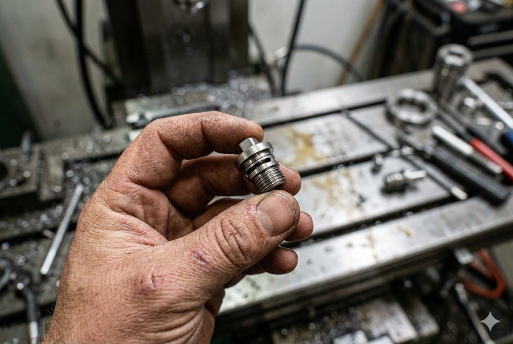
Consider a 50 mm 6061 aluminum 5 shaft held to ±0.005 mm. Aluminum has a CTE of approximately 23 µm/m·°C. A 1°C ambient temperature shift produces:
ΔL = 50 mm × 23 µm/m·°C × 1°C = 1.15 µm = 0.00115 mm
That single degree uses up nearly a quarter of your total tolerance band. A 5°C shift — common in an uncontrolled shop — produces 0.00575 mm of drift, which entirely consumes the tolerance and pushes the part out of spec. This is not a machining problem. It is a physics problem.
Low-CTE materials reduce the sensitivity. Titanium Grade 5 6 at 8.6 µm/m·°C produces less than 40% of the drift aluminum produces under identical temperature conditions.
Material Risk Matrix for Tight-Tolerance Swiss Turning
| Material | CTE (µm/m·°C) | Drift per °C on 50 mm feature | Risk at ±0.005 mm | Notes |
|---|---|---|---|---|
| Titanium Grade 5 | 8.6 | 0.00043 mm | Low | Excellent stability, harder to machine |
| 416 Stainless | 10.0 | 0.00050 mm | Low | Good machinability for stainless |
| 17-4 PH Stainless | 10.8 | 0.00054 mm | Low | High strength, common in aerospace |
| 303 Stainless | 17.0 | 0.00085 mm | Medium | Free-machining, moderate CTE |
| C360 Brass | 19.0 | 0.00095 mm | Medium-High | Easy to machine, higher CTE risk |
| 6061 Aluminum | 23.0 | 0.00115 mm | High | Requires strict thermal management |
Residual Stress Interaction
Material selection also affects residual stress behavior. Parts made from drawn bar stock, ground bar, or heat-treated material carry locked-in stresses from prior operations. When thermal cycling during machining interacts with these stresses, the part may measure in-tolerance immediately after machining but dimensionally shift hours or days later as stresses relax 7 under ambient temperature fluctuation.
Standard first-article inspection will not catch this. A thermal stabilization soak protocol — holding parts at 20°C for a defined period before final measurement — is the correct solution. This should be written into your inspection plan, not left to the supplier's discretion.
How Do I Write a Temperature Reference Condition Into My Drawing or Inspection Spec?
This is where most buyers leave money on the table. They specify the tolerance. They specify the material. But they don't specify the temperature at which the part must be measured — and they assume the supplier will measure at 20°C. Many will not.
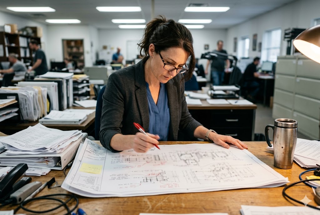
All dimensional inspection of precision Swiss-turned parts must reference ISO 1, which defines 20°C as the international standard temperature for length measurements. Your drawing or inspection spec should explicitly state: "All dimensions apply at 20°C per ISO 1. Pre-shipment inspection reports shall document ambient temperature and part soak time at time of measurement."
Why the Reference Temperature Matters
A Chinese precision machining shop in Guangdong may run at 26–30°C in summer without workshop temperature control. When their CMM operator measures your aluminum Swiss-turned part at 28°C instead of 20°C, the part has dimensionally expanded from its true 20°C geometry. The CMM reads a measurement that does not represent the part's geometry at end-use conditions.
The result is acceptance of parts that are out of tolerance at your facility when measured at 20°C. This is a hidden systematic bias — not random error, not a machine capability problem. It is an inspection temperature problem, and it will repeat consistently until you contractually require measurement at 20°C. The history and technical rationale behind the 20°C standard 8 for industrial length measurement go back to the original ISO 1 recommendation issued in 1954.
Differential CTE Between Part and Measurement Instrument
Even when the shop temperature is consistent, differential CTE between the workpiece material and the measurement instrument introduces systematic error. A steel gage pin measuring an aluminum shaft at 22°C will yield a different error budget than the same gage pin measuring a steel shaft under identical conditions. The gage and the part expand at different rates. CMM accuracy degrades measurably as ambient temperature departs from 20°C, 9 and if both part and instrument are not at 20°C, the measurement result carries embedded thermal error.
This is why CMM rooms in precision shops are temperature-controlled to 20°C ±1°C and why parts are required to soak at that temperature before measurement begins.
Recommended Drawing Note Language
Add the following to your general tolerance block or quality notes:
All dimensions are nominal at 20°C ±1°C per ISO 1. Supplier shall allow minimum 4-hour thermal soak at 20°C ±1°C prior to final dimensional inspection. Pre-shipment inspection reports shall record ambient CMM room temperature and part soak duration at time of measurement.
If your supplier's CMM room is not temperature-controlled, their inspection data is not generated at a defined reference condition. This does not mean the data is useless — but it means you cannot directly compare their results to your incoming inspection results at a controlled 20°C facility. That discrepancy will generate disputes, re-inspection costs, and delivery delays.
Inspection Documentation Requirements to Add to Your PO
| Requirement | Minimum Acceptable | Preferred Specification |
|---|---|---|
| CMM room temperature | 20°C ±2°C | 20°C ±1°C |
| Part soak time | 2 hours minimum | 4 hours minimum |
| Temperature logged on report | Yes | Yes, with timestamp |
| Instrument calibration reference | ISO/IEC 17025 traceable 10 | ISO/IEC 17025 traceable |
| CTE correction applied | Documented if used | Documented with values used |
CNC Thermal Compensation — What It Can and Cannot Do
Modern CNC controls include thermal compensation algorithms that use embedded temperature sensors on machine castings to shift coordinate systems in real time. These systems partially offset machine structure growth during the production run. They are useful. They are not sufficient on their own.
Thermal compensation cannot correct for workpiece material expansion caused by cutting heat. That heat is delivered directly into the part through the cutting zone and the guide bushing — not through the machine structure. Managing workpiece temperature requires coolant management and soak time, not a software offset. A supplier who tells you their CNC thermal compensation eliminates the need for temperature-controlled inspection is giving you a technically incomplete answer.
Conclusion
Thermal expansion is not a subtle variable — it is a measurable, predictable source of dimensional error that either gets controlled or produces rejects. Write the reference temperature into your drawing, specify soak time in your inspection plan, and audit your supplier's thermal management capability before you commit to tight tolerances.
Footnotes
1. Overview of Swiss screw machining processes, guide bushing mechanics, and tolerance capabilities. ↩︎
2. Searchable CTE table and thermal expansion calculator for aluminum, steel, stainless, brass, and titanium. ↩︎
3. Complete guide to PPAP submission levels, documentation requirements, and part approval workflow. ↩︎
4. CMM room temperature, humidity, and layout standards required for accurate dimensional inspection. ↩︎
5. Physical and thermal properties of 6061 aluminum alloy, including CTE value and mechanical characteristics. ↩︎
6. Properties and aerospace applications of Ti-6Al-4V (Grade 5), including its low CTE and dimensional stability. ↩︎
7. How stress relief heat treatment removes machining-induced residual stresses to improve dimensional stability. ↩︎
8. NIST journal article on the 2016 revision of ISO 1 and the history of the 20°C reference temperature standard. ↩︎
9. Hexagon white paper explaining how CMM accuracy degrades with ambient temperature deviation from 20°C. ↩︎
10. ISO's overview of ISO/IEC 17025 accreditation for testing and calibration laboratories and measurement traceability. ↩︎



