 Skip to main content Skip to footer

We source wire EDM parts from factories across China and Vietnam every week. When a client sends drawings with a simple "deburr all edges" note, we often pause — because that instruction can mean very different things depending on the process.
Wire EDM does not produce classical burrs on cut faces because the wire never physically touches the workpiece. The process removes material through thermal erosion, not mechanical shearing. However, edge anomalies can still form at slug separation points, and a separate surface concern — the recast layer — requires its own mitigation strategy that deburring alone cannot solve. Understanding this distinction helps you write better drawings and ask better questions during supplier qualification.
If you are a purchasing manager sourcing precision wire EDM parts, this article will help you specify edge and surface requirements correctly — and avoid costly inspection failures downstream.
Does Wire EDM Naturally Produce Burr-Free Edges, or Are Secondary Operations Required?
Every week our team reviews inspection reports from wire EDM suppliers. The word "burr-free" appears on a lot of drawings, but most buyers do not know what wire EDM actually produces on cut surfaces — and that gap creates real problems at incoming inspection.
Wire EDM cut faces are free of classical mechanical burrs under normal operating conditions. The thermal erosion process produces no plastic deformation on the cut surface. However, a thin recast layer — also called a white layer — forms on every cut face. This layer is brittle, hard, and carries microcracks. It is not a burr, and standard deburring methods do not remove it.
What Is the Recast Layer and Why Does It Matter?
The recast layer 1 is resolidified material that melted during the EDM spark cycle and re-fused onto the cut face before it could be fully flushed away by the dielectric fluid. It is typically 5–25 µm thick, depending on cutting parameters.
This layer has three properties that affect part performance:
| Property | Recast Layer Behavior | Why It Matters |
|---|---|---|
| Hardness | Higher than base material | Resists finishing; can cause tool wear in post-processing |
| Residual stress | Tensile | Promotes crack initiation under cyclic load |
| Microcrack density | Moderate to high | Reduces fatigue life; risk of crack propagation |
For general mechanical components used in static applications, the recast layer is usually acceptable. For fatigue-critical parts 2 — aerospace brackets, tooling under cyclic load, medical implants — it must be removed.
Where Can Physical Burrs Still Form?
True physical burrs on wire EDM parts are rare, but they do occur at two specific locations:
Start-hole junction: The wire must be threaded through a pre-drilled start hole. At the point where the wire path begins cutting, a small witness mark or step can form if the entry is not managed cleanly.
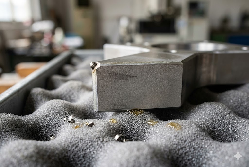
Slug separation cutoff tab: When cutting a slug (a fully enclosed shape), the wire leaves a small tab of uncut material to prevent the slug from dropping mid-cut. When this tab is finally cut and the slug is separated, a nub or step artifact can remain. This requires manual cleanup — typically a fine file, a hard Arkansas stone, or a razor blade on soft materials.
Skim Passes: The Primary Process Control
The main in-process control for recast layer thickness is skim passes (trim cuts). After the main rough cut, the wire makes additional passes at progressively lower energy settings. The relationship between skim passes and surface finish 3 is well-documented across material types.
| Number of Skim Passes | Typical Surface Finish (Ra) | Approx. Recast Thickness |
|---|---|---|
| 0 (rough cut only) | Ra 2.0–3.2 µm | 15–25 µm |
| 1 skim pass | Ra 1.0–1.6 µm | 10–15 µm |
| 2 skim passes | Ra 0.4–0.8 µm | 5–10 µm |
| 3+ skim passes | Ra 0.2–0.4 µm | < 5 µm |
This matters for procurement: Chinese and Vietnamese EDM shops will sometimes omit skim passes to reduce cycle time and keep their quote competitive. A dimensional CMM report will not detect this. The part will measure correctly but the surface quality will be degraded. Specifying a minimum skim-pass count in your purchase order, and asking for machine parameter logs, is the only reliable way to verify compliance.
How Should I Specify Edge Break and Deburring Requirements on My Drawing?
When our team helps clients finalize drawings before sending them to suppliers, edge and surface notes are among the most commonly under-specified areas. Vague instructions lead to inconsistent results and inspection disputes.
Edge break and surface condition on wire EDM parts should be specified with three distinct callouts: a recast layer depth limit with a verification method, a skim-pass count requirement, and a separate edge condition note for slug separation points. Generic "deburr per drawing" notes are not enforceable for wire EDM and will not prevent recast-related failures.

Three Specification Elements You Need
Most drawings cover only one of these three elements — usually the least important one. Here is what a complete edge specification should include:
Element 1 — Recast Layer Depth Limit
State a maximum acceptable recast layer depth and the verification method. A practical callout reads:
"Recast layer not to exceed 10 µm on all EDM cut faces. Verification by metallographic cross-section per ASTM E3 4 or electropolish stock removal log."
For non-critical parts, 15 µm is a common acceptance limit. For fatigue-critical parts, 5 µm or less is appropriate.
Element 2 — Skim-Pass Requirement
State a minimum number of skim passes in the process specification or purchasing notes. For tight-tolerance parts, two skim passes minimum is a reasonable baseline.
Element 3 — Slug Separation Edge Condition
Specify what is acceptable at cutoff tab locations. Options include:
| Callout Option | Meaning | When to Use |
|---|---|---|
| "No witness marks at cutoff tab" | Surface must be flush with nominal geometry | Sealing faces, mating surfaces |
| "Step at cutoff ≤ 0.05 mm" | Small nub is acceptable within tolerance | Non-functional surfaces |
| "Manual stone finish at cutoff tab" | Light hand finishing is acceptable | General mechanical parts |
What About GD&T Edge Break Callouts?
A standard edge break callout — for example, "0.1–0.3 mm chamfer or radius, all EDM edges" — is appropriate for corners produced by wire EDM cuts. It controls the sharpness of the corner geometry and is measurable by CMM or optical comparator.
This callout does not address the recast layer. Both callouts are needed on the same drawing if both properties matter.
A Note on Drawing Revision
If you are working from drawings that were originally designed for milled or turned parts and later re-routed to wire EDM 5, review the edge and surface notes carefully. "Deburr and break all sharp edges" is a standard milling note. Applied to wire EDM, it is misleading and may cause the supplier to spend time on unnecessary manual deburring while ignoring the recast layer entirely.
What Deburring Method Is Safest for Tight-Tolerance Wire EDM Parts — Manual or Vibratory?
This question comes up regularly when clients are managing incoming inspection and find a small edge anomaly on an otherwise conforming part. The instinct is to deburr it. But on a tight-tolerance wire EDM part, the wrong deburring method can do more damage than the anomaly itself.
For tight-tolerance wire EDM parts, manual deburring with a fine hand stone or razor blade is safer than vibratory finishing because it allows precise, localized material removal without affecting critical dimensions. Vibratory finishing removes material uniformly across all surfaces and can violate tolerances on thin walls or precision features.

Understanding What Needs to Be Removed
Before selecting a method, identify what you are actually trying to remove:
- Nub at slug separation point: A small step or raised feature from the cutoff tab. This is the most common edge anomaly on wire EDM parts.
- Brass wire contamination: Micro-particles of brass wire embedded in the surface during cutting. Not visible to the naked eye. Detectable by XRF analysis 6.
- Recast layer: The 5–25 µm white layer on cut faces. Not removable by mechanical deburring.
Each of these requires a different approach. Treating them all as "deburring" is where errors occur.
Method Comparison
| Method | Best For | Risk on Tight-Tolerance Parts | Stock Removal |
|---|---|---|---|
| Hand stone / razor blade | Slug separation nubs | Low — operator controls exactly where material is removed | <0.01 mm with care |
| Glass bead blasting (low pressure) | Brass wire contamination, surface debris | Low — minimal dimensional impact with fine media | Negligible |
| Vibratory finishing | General mechanical parts, no tight tolerances | High — removes material from all surfaces including reference faces | 0.01–0.05 mm per pass |
| Electropolishing | Recast layer removal, surface finish improvement | Low — controlled, measurable stock removal | ±0.005 mm per cycle |
| Barrel tumbling | Bulk low-tolerance parts | High — unpredictable on complex geometries | Variable |
When Electropolishing Is the Right Choice
Electropolishing 7 is the preferred post-process for removing the recast layer on functional wire EDM surfaces. It removes material electrochemically from the entire surface at a controlled rate — typically 0.003–0.010 mm per cycle — and simultaneously improves surface finish by up to 50%.
For parts going into food contact, medical, or high-purity fluid applications, electropolishing also removes embedded brass wire contamination and surface debris. A COA documenting stock removal and surface finish before and after is standard documentation for these applications.
What Not to Do
Avoid aggressive mechanical methods — grinding, abrasive belts, or coarse vibratory media — on wire EDM parts with tolerances tighter than ±0.05 mm. These methods remove stock unpredictably and can alter the geometry of fine features, internal radii, and thin walls that wire EDM was specifically chosen to produce.
If a supplier proposes vibratory finishing on a tight-tolerance wire EDM part without first identifying which features are non-critical, ask them to pause and review the drawing with you.
Should Deburring and Edge Condition Be Verified During Pre-Shipment Inspection?
Our quality team conducts pre-shipment inspections on wire EDM parts before they ship from China and Vietnam. Edge condition is one of the areas where we consistently find gaps between what the drawing specifies and what the factory actually delivers — not because the factory is dishonest, but because the inspection criteria were never clearly defined.
Yes — edge condition and surface quality should be explicitly included in the pre-shipment inspection checklist for wire EDM parts. Dimensional CMM reports alone will not detect recast layer non-compliance, missing skim passes, or slug separation artifacts. These require dedicated inspection steps with defined acceptance criteria stated in the inspection plan before production begins.

What a CMM Report Does and Does Not Cover
A dimensional CMM report is the standard deliverable from most wire EDM suppliers. It verifies that the part geometry is within the drawing tolerances. It is valuable and necessary. But it has clear limits:
- It does not measure recast layer depth.
- It does not detect brass wire contamination.
- It does not verify that skim passes were performed.
- It does not assess slug separation artifacts unless these are explicitly dimensioned on the drawing.
This means a part can pass CMM inspection and still have a recast layer two to three times thicker than the specified limit.
Building an Effective Inspection Checklist
For wire EDM parts, the inspection plan should include the following steps:
Step 1 — Dimensional Verification
CMM or optical comparator check against all drawing tolerances. Standard practice for most suppliers.
Step 2 — Surface Finish Measurement
Contact profilometer or white-light interferometer 8 measurement of Ra on all specified cut faces. Verify against drawing callout.
Step 3 — Recast Layer Verification (if specified)
Either request a metallographic cross-section report from the supplier, or require an electropolish stock removal log documenting material removed per cycle. For high-volume orders, one cross-section sample per batch is a practical approach.
Step 4 — Slug Separation Edge Inspection
Visual and tactile inspection of all cutoff tab locations. Use a loupe or bench microscope for features smaller than 2 mm. Verify against the drawing callout (flush, step ≤ X mm, or stone finish).
Step 5 — Brass Contamination Check (application-specific)
For food contact, medical, or high-purity fluid applications, require XRF spot analysis 9 on cut faces. This step can be added to the supplier's in-process inspection or performed at incoming inspection.
Communicating Inspection Requirements to Suppliers
The earlier you communicate inspection requirements, the better. Suppliers who receive an inspection checklist at order placement have time to build the required steps into their process. Suppliers who receive it at pre-shipment inspection often cannot comply — because the process parameters were never set up to meet the criteria.
Our team includes inspection criteria in the purchase order, not just on the drawing. This creates a contractual basis for the inspection findings and avoids disputes at shipment. Understanding EDM surface integrity 10 from the process side helps buyers ask the right questions when reviewing supplier documentation.
Conclusion
Wire EDM is a precision process, but "burr-free" does not mean "specification-free." Write explicit recast layer limits, require skim-pass counts, and include surface verification in your inspection plan. These steps are the difference between parts that conform on paper and parts that perform in the field.
Footnotes
1. ScienceDirect overview of EDM recast layer (white layer) formation, properties, and microstructural effects. ↩︎
2. Peer-reviewed study on how EDM recast layers cause fatigue degradation in aerospace-critical components. ↩︎
3. Technical guide to wire EDM surface finish, skim pass strategies, and Ra targets by material type. ↩︎
4. ASTM E3 standard guide for preparation of metallographic specimens used in recast layer cross-section verification. ↩︎
5. Xometry resource explaining wire EDM process principles, tolerances, and post-processing considerations. ↩︎
6. Applied Technical Services overview of XRF analysis for non-destructive detection of metal surface contamination. ↩︎
7. Wikipedia reference on electropolishing: the electrochemical process used to remove recast layers and improve surface finish. ↩︎
8. ScienceDirect overview of wire EDM process parameters and their effect on surface measurement and integrity. ↩︎
9. Thermo Fisher guide on using portable XRF analyzers safely for metal surface composition analysis. ↩︎
10. MoldMaking Technology article explaining the EDM altered metal zone and its effect on mold surface integrity. ↩︎



