 Skip to main content Skip to footer
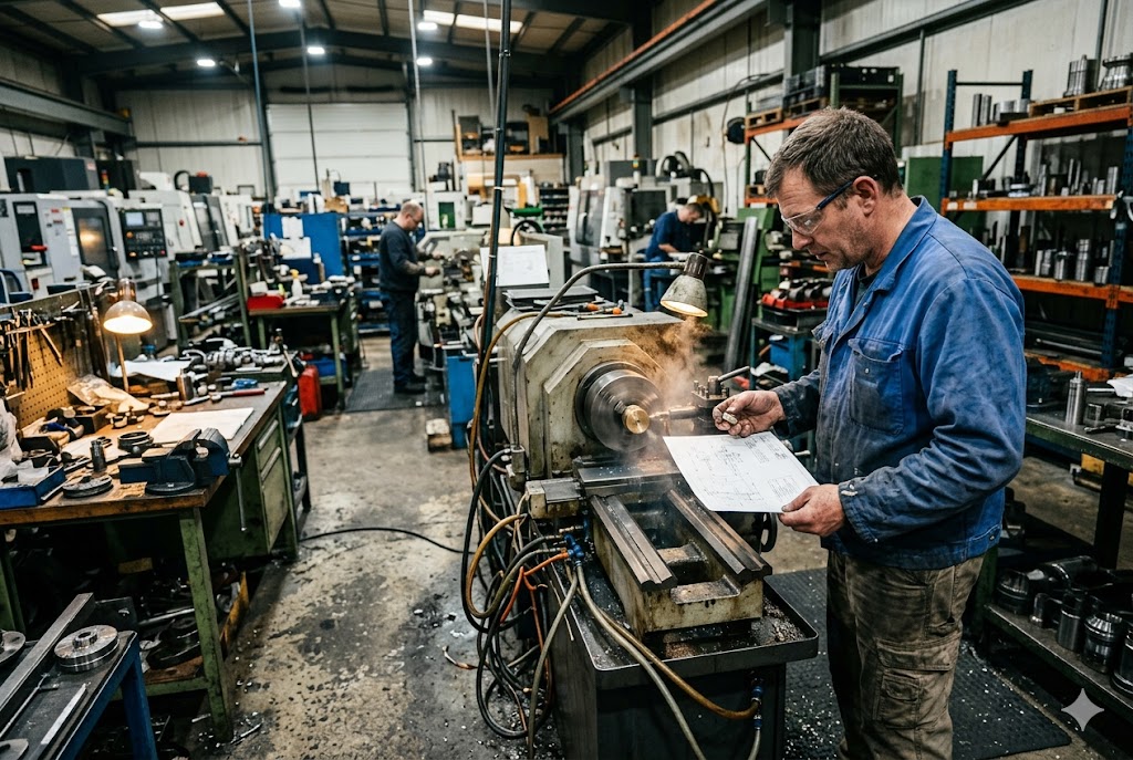
When our engineers sit down with a new drawing, the first thing we check is whether the GD&T callouts match how a Swiss lathe actually holds and cuts the part. If they don't, problems start fast.
To apply GD&T correctly for Swiss-type lathe machining, set Datum A as the OD at the guide bushing contact zone, use runout (not concentricity) for round features, apply true position for cross-drilled holes, and place the secondary datum on a real machined feature, never the cutoff face.
Let's break this down step by step, starting with the controls that matter most.
Which GD&T Controls (Runout, Concentricity, Cylindricity) Are Most Critical for Swiss-Turned Parts?
Our shop floor team reviews dozens of drawings every month, and we keep seeing the same controls cause confusion. Some callouts work great on a Swiss lathe. Others cause delays before the first part even gets cut.
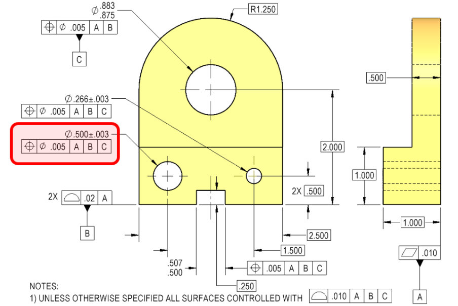
Runout is the most critical GD&T control for Swiss-turned parts. Circular runout checks single cross-sections, while total runout checks a full surface against Datum A. Cylindricity matters for long parts. Concentricity should be avoided.
Why Runout Fits Swiss Machining So Well
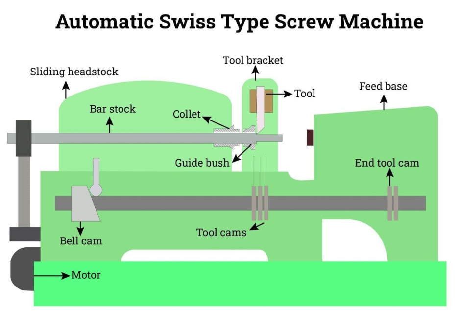
A Swiss lathe holds the bar through a guide bushing 1. The bushing acts as a tight sleeve around the part. This means the part's axis is set by the bushing, not by a chuck. Runout callouts measure how much a feature wobbles around that axis. That makes runout a natural match for the process.
Circular runout checks one ring, or cross-section, of the part. Total runout checks the entire surface along its length. We use circular runout 2 for things like a single groove diameter. We use total runout for a full bearing journal or a long OD that must stay straight and round across its whole length.
Where Cylindricity Comes In
Cylindricity becomes important on long, thin parts. Swiss machining often produces parts with a high length-to-diameter ratio. Bar stock is rarely perfectly straight. Guide bushings wear over time. Both factors add up. The result can be a barrel shape or a slight taper, even if every diameter measures within tolerance at each point.
A plus-or-minus size tolerance alone cannot catch this kind of error. Cylindricity 3 adds a 3D check across the whole surface. We recommend it for any OD with an L/D ratio above 4:1, especially on shafts that must seat into a bearing or bushing.
Why Concentricity Should Be Avoided
Concentricity sounds like a good fit for round parts, but it causes more harm than good. Concentricity requires finding the median point of opposite surface points around an axis. This needs a CMM and special software. Most shop floors cannot check it during production. ASME Y14.5-2018 4 moved away from concentricity for this exact reason.
| GD&T Control | Best Use on Swiss Parts | Inspection Method |
|---|---|---|
| Circular Runout | Single diameter or groove | Bench runout stand |
| Total Runout | Full OD or face vs. Datum A | Bench runout stand with V-block |
| Cylindricity | Long ODs, L/D > 4:1 | CMM or optical comparator |
| Concentricity | Avoid; replace with runout | CMM only (not shop-floor friendly) |
Quick Comparison Table
| Old Callout | Better Swiss-Friendly Alternative | Reason |
|---|---|---|
| Concentricity 0.02 | Total Runout 0.02 to Datum A | Same intent, easy to check |
| Position with no datum | True Position with Datum A + B | Removes inspection ambiguity |
| Profile of a surface | Profile of a line | Matches 2D cross-section cuts |
How Do I Use a Datum Reference Frame on a Swiss-Turned Part Drawing to Avoid Inspection Ambiguity?
I've opened more than one drawing where the datum frame just didn't match how the part gets cut. When that happens, our quality team and the customer's engineer end up on a call trying to figure out what the designer actually meant.
Build the datum reference frame around the actual machining sequence: Datum A is the OD at the guide bushing, Datum B is the first machined shoulder or groove from the bar-feed end, and Datum C, if needed, locks rotational orientation for milled or drilled features.
Datum A Comes First, Always
On a Swiss lathe, the bar feeds through the guide bushing 5 and the cutting tools work close to that bushing face. This is the real physical constraint during machining. Datum A should be the OD section that sits inside or right next to the bushing. Every runout, position, and profile callout should reference back to this datum, directly or indirectly.
Datum B Must Be a Real Feature, Not the Cutoff Face
This is where Swiss machining differs from standard turning. The cutoff face, the very last surface cut on the part, has no positional control during the cut. It cannot serve as a datum because nothing locates against it while the tool parts the bar.
Instead, pick the first shoulder, groove, or step cut from the bar-feed end as Datum B. This feature exists early in the machining sequence 6 and gives inspection a real, repeatable surface to reference.
Building the Frame Step by Step
| Step | Action | Why It Matters |
|---|---|---|
| 1 | Identify the bushing contact OD | Sets Datum A, the true machining axis |
| 2 | Find the first shoulder or groove from bar-feed end | Sets Datum B, avoids cutoff face ambiguity |
| 3 | Add Datum C only if rotation matters | Needed for cross-drilled or milled features |
| 4 | Apply FCFs referencing A, B (and C) | Removes guesswork for QC team |
Avoiding the "Floating Tolerance" Problem
When a datum frame is missing or built around the cutoff face, every downstream feature gets a "floating" tolerance. The QC team has to guess which surface to clamp against. Different inspectors may pick different setups, and the same part can pass or fail depending on who measures it. A correct datum frame, tied to the real machining order, removes this guesswork completely.
For parts with secondary operations like grinding or plating, keep the same Datum A and B after the operation. Re-check runout and cylindricity against these same datums post-grind. For plated parts, build the plating thickness into the pre-plate size tolerance so the final part still falls inside the runout zone after coating.
Can a Chinese Factory's QC Team Interpret ASME Y14.5 GD&T Callouts Without Additional Explanation?
Over the years, we've trained QC staff across our China and Vietnam facilities on ASME Y14.5. I won't pretend every shop in China has this skill level, because many don't.
Many Chinese factory QC teams can read basic GD&T symbols like flatness and runout, but complex callouts such as profile, true position with multiple datums, or composite tolerances often need extra notes, sample sketches, or a short call to avoid misreading.
The Skill Gap Is Real, But Uneven
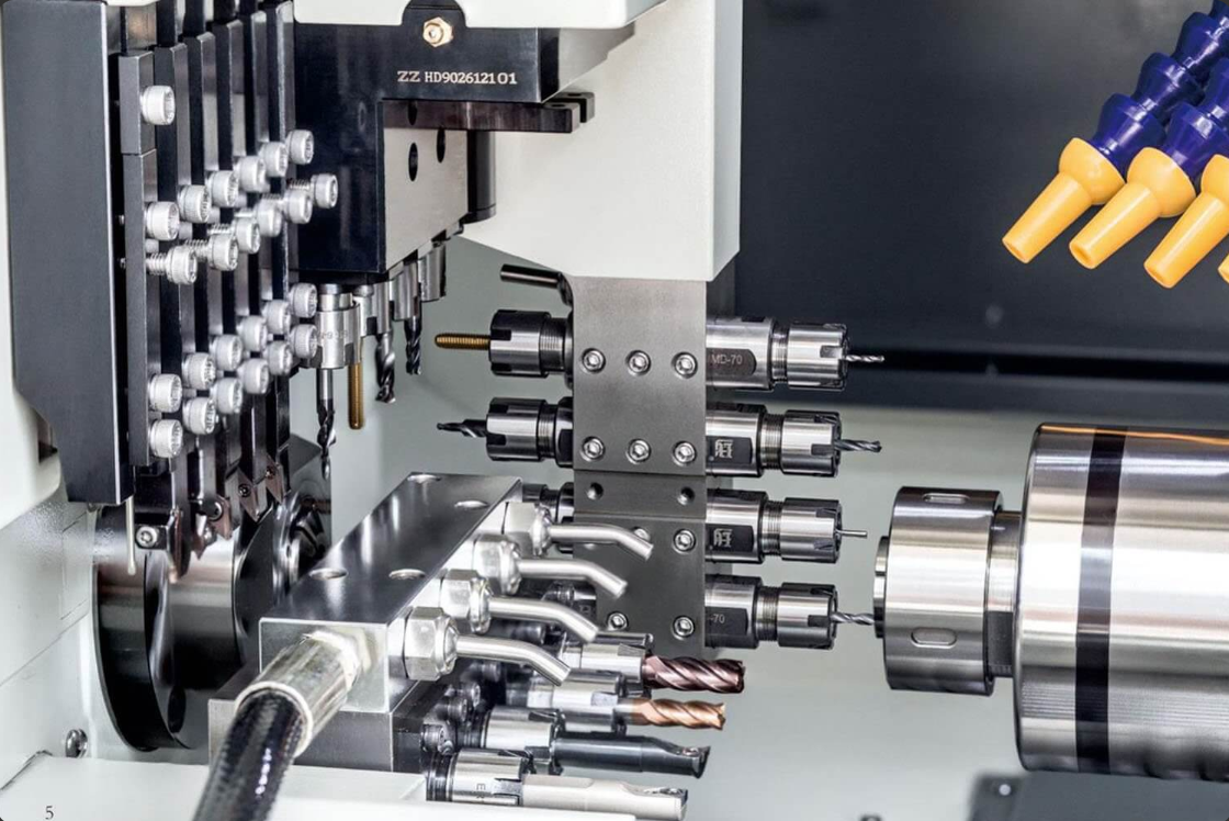
Larger factories that work with US and European clients regularly tend to have QC staff trained on ASME Y14.5. Smaller shops, especially those focused on domestic Chinese clients, often use older national standards or simplified tolerancing. Their teams may know the basic symbols, like flatness, parallelism, and runout, but struggle with combined callouts 7.
Common Misreads We've Seen
| GD&T Callout | Common Misread | Result |
|---|---|---|
| Total runout vs. Datum A | Read as size tolerance only | Wobble not checked |
| True Position (cylindrical zone) | Read as plus/minus on each axis | Wrong tolerance zone shape |
| Profile of a line | Treated as profile of surface | Wrong measurement tool used |
| Composite FCF (two-row) | Only top row checked | Pattern location error missed |
How We Close the Gap
A drawing alone is often not enough. We add a short note block in plain English next to complex FCFs. For example, next to a true position callout, we write "check with pin gauge, axis must fall inside the circle shown." This single line prevents a lot of confusion.
We also build a one-page inspection guide for first-run parts. This guide shows each GD&T symbol on the drawing, paired with a photo of the actual gauge or tool used to check it. New QC staff can follow this guide without needing to fully understand the ASME standard from scratch.
What Buyers Can Do
Buyers can help by asking suppliers for a first article inspection report 8 before full production starts. This report shows how the supplier interpreted each callout. If the supplier checked the wrong thing, the buyer catches it on one sample part, not on a full batch of 5,000 pieces.
What GD&T Mistakes on a Drawing Commonly Cause Quoting Errors or Production Disputes in China?
I've seen quotes come back two or three times higher than expected, all because of one small GD&T mistake on a drawing. These mistakes cost time for everyone before a single part gets made.
Common GD&T mistakes that cause quoting errors or disputes in China include missing or unclear datums, tolerances tighter than the feature needs, using deprecated symbols like concentricity, and applying form controls that can't be checked with shop-floor tools.
Mistake 1: Missing or Unclear Datums
When a drawing has tight position or runout callouts but no clear datum frame, the factory has two choices. They either guess, which leads to disputes later, or they ask for clarification, which delays the quote. Some factories quote high "just in case," assuming the worst-case fixturing setup 9.
Mistake 2: Tolerances Tighter Than the Function Needs
A 0.005 mm runout tolerance on a non-critical OD sounds precise, but it may force the factory to add a grinding step that wasn't needed. This raises the quote and the lead time. We always ask: does this surface touch a bearing, seal, or mating part? If not, a looser tolerance often works fine and keeps the price down.
Mistake 3: Deprecated or Unclear Symbols
Concentricity callouts, as covered earlier, often get quoted with a hidden CMM inspection cost, or worse, get ignored entirely because the shop has no way to check it. Either outcome leads to a dispute: either the price is higher than expected, or the part fails the customer's own inspection later.
Mistake 4: Form Controls That Don't Match the Fixture
Perpendicularity and angularity callouts 10 assume a true datum plane. A collet or V-block fixture, common on Swiss lathes, cannot create this kind of flat reference surface. When a drawing calls for perpendicularity on a face that will be held in a collet, the factory either cannot check it properly, or needs a special fixture that adds cost.
Common Mistakes and Their Impact
| Mistake | Impact on Quote | Impact on Production |
|---|---|---|
| Missing datum frame | Higher "safety margin" pricing | Inspection disputes later |
| Over-tight tolerance on non-critical feature | Unnecessary grinding cost | Longer lead time |
| Concentricity instead of runout | Hidden CMM cost or skipped check | Parts fail customer audit |
| Perpendicularity in collet-held setup | Special fixture cost | Delayed first article approval |
How to Prevent These Issues Before Quoting
The best fix happens before the RFQ goes out. A short pre-quote review, where an engineer checks the datum frame, the tolerance values against the part's function, and the inspection method for each callout, can catch most of these issues. This review takes maybe thirty minutes but can save weeks of back-and-forth later.
Conclusion
Clear datums, correct controls, and shop-friendly callouts prevent quoting errors and disputes on Swiss-turned parts.
Footnotes
1. Explains how the guide bushing defines the Swiss lathe machining axis. ↩︎
2. Defines circular runout and how cylindrical parts are inspected for it. ↩︎
3. Explains cylindricity callouts, measurement, and tolerance zones in GD&T. ↩︎
4. Compares ASME Y14.5-2018 to ISO GPS and notes deprecated symbols. ↩︎
5. Describes how the guide bushing supports the workpiece during cutting. ↩︎
6. Step-by-step guide to building a datum reference frame in GD&T. ↩︎
7. Detailed explanation of true position and feature control frames. ↩︎
8. Guide to first article inspection reports and their role in QC. ↩︎
9. Background on datum reference frames and fixturing for inspection. ↩︎
10. Explains perpendicularity tolerance zones and datum requirements. ↩︎



