 Skip to main content Skip to footer
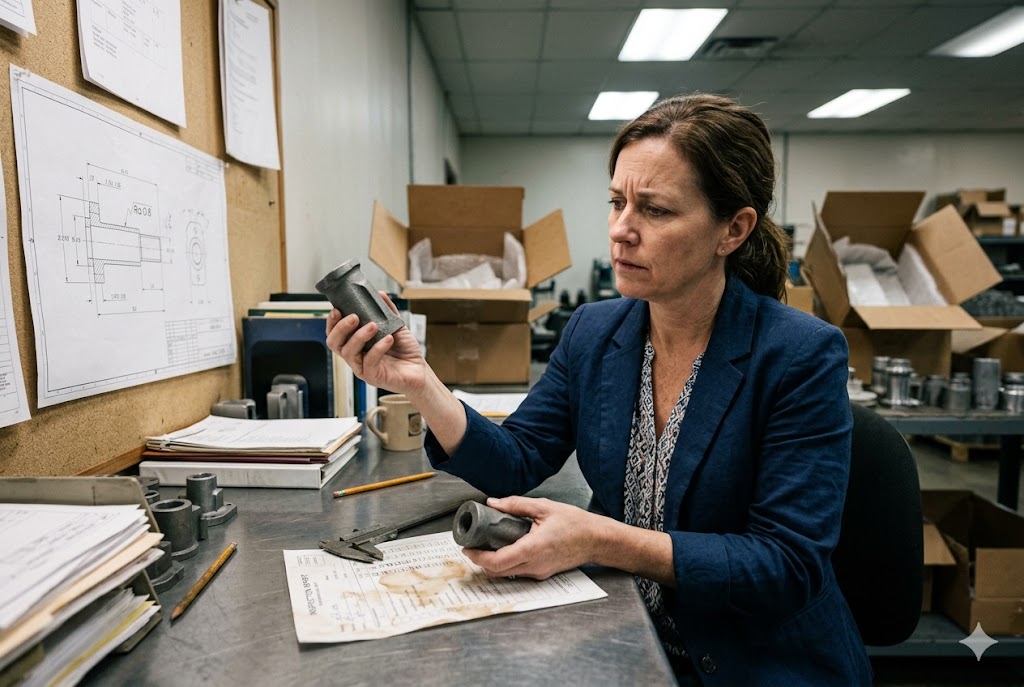
We have seen this situation many times across our supply chain operations: a customer sends a drawing with the note "sandblast finish, smooth and clean." The parts arrive looking completely different from what was expected. That one vague note costs time, money, and trust.
Sandblasting and polishing requirements must be standardized using international grade designations, quantified Ra or Rz values, defined abrasive media specifications, and a physical golden sample. Using descriptive language like "smooth" or "clean" alone is unenforceable and leads to supplier misinterpretation in almost every case.
If you are sourcing custom mechanical parts from China or Vietnam, getting surface finish right the first time saves you from costly rework, shipment delays, and production stoppages on your end.
What Reference Standards or Visual Aids Should I Provide to Define a Sandblast Finish Level?
When our team prepares technical packages for suppliers, we always include more than just a drawing. We have learned that words like "clean" or "rust-free" mean different things in different shops.
To define a sandblast finish level, specify the ISO 8501-1 Sa grade or its SSPC/NACE equivalent directly on the drawing. For most industrial applications, Sa 2.5 (SSPC-SP10, near-white metal) is the standard minimum. Always cross-reference the GB/T 8923-2011 equivalent for Chinese suppliers to close the interpretation gap.

Why Descriptive Language Fails
Words like "clean," "blasted," or "rust-free" are not standards. They are opinions. Every shop interprets them differently. A QC inspector at a Chinese factory is trained on GB/T 8923-2011 — not ISO 8501-1 and not SSPC. If your drawing only calls out ISO or SSPC grades without providing the GB equivalent, the supplier defaults to their own domestic interpretation. That interpretation may not match yours.
Here is a simple cross-reference table for the most common grades:
| ISO 8501-1 Grade | SSPC Equivalent | NACE Equivalent | GB/T 8923-2011 | Description |
|---|---|---|---|---|
| Sa 1 | SSPC-SP7 | NACE 4 | Sa 1 | Brush-off blast |
| Sa 2 | SSPC-SP6 | NACE 3 | Sa 2 | Commercial blast |
| Sa 2.5 | SSPC-SP10 | NACE 2 | Sa 2½ | Near-white metal blast |
| Sa 3 | SSPC-SP5 | NACE 1 | Sa 3 | White metal blast |
For maximum clarity in international specifications, always list both the ISO/SSPC designation and the GB equivalent in your drawing notes or referenced process specification. The ISO 8501-1 cleanliness grades 1 define four blast levels, Sa 1 through Sa 3, each with distinct visual and contamination criteria — and industry data consistently shows that surface preparation is the single most important factor determining coating system durability. This one step eliminates most shop-floor confusion.
Define the Anchor Profile Depth
Cleanliness grade alone is not enough. Two surfaces can both pass Sa 2.5 while having very different anchor profiles — the microscopic peaks and valleys left by blasting. This matters for coating adhesion, contact behavior, and functional performance.
Define the anchor profile using ISO 8503 2 or ASTM D4417 methods. The measurement is expressed as Rz (peak-to-valley height) in micrometers.
| Abrasive Media | Typical Anchor Profile (Rz) | Common Use Case |
|---|---|---|
| Fine glass bead | 25–35 µm | Cosmetic or light-duty surfaces |
| Medium steel grit | 50–70 µm | Standard industrial coating prep |
| Coarse steel grit | 75–100 µm | Heavy-duty anti-corrosion coating |
| Aluminum oxide | 40–60 µm | Hard surfaces, precision parts |
A fine glass bead and a coarse steel grit can both achieve Sa 2.5 cleanliness. But their anchor profiles are completely different. This changes how coatings bond and how surfaces perform under contact. Specify the profile depth, not just the grade.
Specify the Abrasive Media
"Sandblasting" allows the supplier to use any abrasive media — glass bead, steel shot, steel grit, aluminum oxide, or even garnet. Each produces a different surface texture and profile. Specify the media type, grit size or mesh size, and hardness in your drawing notes or process spec.
Use Visual Aids and Golden Samples
A written spec is necessary. It is not sufficient on its own. Suppliers work better with something they can hold and compare. A physical golden sample — signed, serialized, and stored at both your facility and the supplier's — is the primary enforcement reference. It communicates texture, uniformity, and appearance in a way no written spec can.
Require your Pre-Shipment Inspection (PSI) inspector to compare production parts against the golden sample before shipment sign-off. Surface finish is one of the most frequently misrepresented parameters in supplier QC packages.
How Do I Specify Polishing Grit Sequence and Final Ra Value for Cosmetic Wire EDM Surfaces?
Our engineers have dealt with this exact scenario on cosmetic mold inserts and precision fixture parts. A surface that looks "polished" under the shop light at the factory can look completely wrong under the customer's inspection lamp. The problem is almost always undefined Ra targets and missing grit sequence callouts.
To specify polishing for cosmetic wire EDM surfaces, define the complete grit sequence on the process spec or drawing, call out the final Ra value using ISO 1302 conventions with measurement cut-off length, and add a note clarifying whether the Ra is measured before or after any subsequent surface treatment such as anodizing or plating.

Replace Subjective Terms with Measured Values
Terms like "mirror finish," "shiny," "smooth," and "polished" are not specifications. They are descriptions. They are unenforceable. Two suppliers reading "mirror finish" will deliver two different surfaces.
Replace every subjective surface term with a quantified Ra or Rz value per ISO 1302 3. Include the measurement parameter, the numeric limit, and the cut-off length. For example:
- Ra ≤ 0.4 µm, cut-off λc = 0.8 mm (for fine cosmetic surfaces)
- Ra ≤ 0.1 µm, cut-off λc = 0.25 mm (for optical or near-mirror finishes)
- Ra ≤ 1.6 µm, cut-off λc = 0.8 mm (for general machined surfaces)
Use a title block note for all unspecified surfaces (for example: "Unspecified surfaces: Ra 3.2 µm") and use ISO surface texture symbols for feature-level callouts on critical faces only.
Define the Grit Sequence
Wire EDM surfaces 4 have a characteristic recast layer and surface texture. Polishing out that texture to a cosmetic finish requires a controlled sequence of abrasive grits, moving from coarser to finer steps. If you do not specify the sequence, the supplier may skip steps, producing a surface that measures the correct Ra by averaging but still shows visible scratches or directionality under angled light.
A typical grit sequence for cosmetic EDM surfaces might look like this:
| Step | Grit / Tool | Purpose |
|---|---|---|
| 1 | 180–240 grit stone | Remove recast layer and EDM marks |
| 2 | 320–400 grit stone | Reduce scratches from step 1 |
| 3 | 600 grit paper or stone | Refine surface, reduce Ra toward target |
| 4 | 800–1200 grit paper | Approach final finish level |
| 5 | Diamond paste 3–6 µm | Final polishing, achieve Ra ≤ 0.4 µm or finer |
| 6 | Diamond paste 1 µm | Near-mirror, Ra ≤ 0.1 µm |
Not every part needs all six steps. Define which steps apply to your part based on the required Ra target. The multi-stage polishing process from EDM to mirror finish 5 must progress from coarse lapping to remove the EDM recast layer before finer diamond paste stages can produce a consistent cosmetic result — skipping steps creates an averaging illusion in Ra measurements while visible scratch patterns remain.
Specify Lay Direction
Lay direction is the orientation of the polishing marks left on the surface. It matters on sealing faces, sliding contact surfaces, and cosmetic exteriors. Omitting lay direction gives the supplier freedom to orient polishing passes in any direction.
Use ISO 1302 lay symbols on the drawing:
=Parallel to the surface boundary⊥Perpendicular to the surface boundaryXCrossed (two directions)MMultidirectional (non-directional, random)CCircular
On sealing surfaces, a non-directional or circular lay is often required. On sliding surfaces, the lay direction relative to the sliding axis affects friction and wear. Do not leave this undefined.
Pre- vs. Post-Treatment Measurement
One of the most common sources of first-article rejection disputes is confusion over when to measure the surface finish. If your part is polished and then anodized, the Ra value changes after the anodizing layer is applied. Your drawing must state clearly: "Ra ≤ 0.4 µm after polishing, prior to anodizing." This removes all ambiguity about at which stage the supplier is responsible for conformance. As one engineering guide notes, requirements specifying Ra values before or after coating must be explicitly declared 6 on the drawing — otherwise the inspector has no way to determine which production state to measure.
Should I Send a Physical Reference Sample to the Supplier to Define the Finish Standard?
Yes. We consider this mandatory, not optional. Our team has seen too many cases where written specs were followed precisely on paper but the delivered surface finish still failed visual inspection. A physical reference sample closes the gap that words cannot.
Yes, you should always send a physical golden sample to define the finish standard. The sample must be signed, serialized, and stored at both your facility and the supplier's. One sample per distinct surface condition is required — one for each sandblast grade and one for each polishing level — and the golden sample, not the written spec, is the primary enforcement reference.

Why Written Specs Are Not Enough
Written specifications define what is required. They do not communicate texture, sheen, directionality, uniformity, or the visual character of a surface. A polished surface at Ra 0.4 µm can still look wrong if the lay direction is inconsistent or the surface has micro-scratches that average out in the Ra measurement. A sandblasted surface at Sa 2.5 can still look patchy or uneven if the operator's technique is inconsistent.
The human eye detects surface anomalies that a profilometer does not capture. That is why cosmetic parts — panels, housings, fixtures, mold inserts — require a visual reference that QC can hold next to the production part. The Ra and Rz parameters defined under ISO 4287 7 measure amplitude averages across a sampling length — but Ra in particular does not differentiate between peaks and valleys and carries relatively limited information about surface character. This is precisely why a physical golden sample remains the definitive acceptance reference for cosmetic parts.
How to Manage Golden Samples
A golden sample is only useful if it is actively managed. Here is a practical process:
Step 1 — Create the sample. Produce or obtain a part that represents the exact surface condition you require. This may be a pre-production sample, a first-article part, or a specially produced reference piece.
Step 2 — Sign and serialize it. Label the sample with a unique serial number. Both you and the supplier sign a document stating that this sample defines the acceptance standard.
Step 3 — Store duplicates. Keep one signed copy at your facility. Send one signed duplicate to the supplier. The supplier must store it at their QC station, not in a drawer.
Step 4 — Reference it in the drawing or PO. Add a note to your drawing or purchase order: "Surface finish to conform to golden sample [Serial No. XYZ]." This makes the sample a contractual reference.
Step 5 — Refresh as needed. Physical samples degrade over time. Polished samples can oxidize or get scratched. Replace them periodically and re-sign the replacement.
Tie Payment to Golden Sample Sign-Off
Surface finish must be a named hold-point in your payment release schedule. Many purchasing teams focus QC checklists on dimensional conformance, passing CMM data, and then releasing payment — while surface finish is treated as a secondary check or skipped entirely. This is how non-conforming surface conditions get into shipments.
Tie at least one payment milestone to first-article sign-off on surface finish. If the surface does not match the golden sample, payment does not release. This is the clearest signal to the supplier that surface finish is a serious requirement, not a preference.
Third-Party Verification
Do not rely on supplier self-reported surface data. Require your Pre-Shipment Inspector to perform independent verification at the supplier's facility before shipment sign-off. For polished surfaces, this means profilometer measurement. For blasted surfaces, this means Testex Press-O-Film tape for anchor profile depth. Self-reported data from suppliers on surface finish is one of the least reliable data points in a Chinese supplier's QC package. A structured pre-shipment inspection 8 program using AQL sampling includes surface defect checks and color/finish comparison against an approved reference sample — making it the last reliable quality gate before goods leave the factory.
How Do I Inspect Sandblast or Polishing Uniformity During Pre-Shipment Quality Checks?
Our QC team conducts pre-shipment inspections at supplier facilities regularly. Surface finish uniformity is one of the first things we check — and one of the most frequently found non-conformances. Knowing what to check and how to check it makes a significant difference in what you catch before parts are loaded into a container.
To inspect sandblast or polishing uniformity during pre-shipment checks, use Testex Press-O-Film tape for blasted anchor profile depth, a calibrated profilometer for Ra measurement on polished surfaces, and a signed golden sample for visual comparison. Surface finish must be a named hold-point, not a secondary check performed after dimensional sign-off.

Tools Required for Surface Finish Inspection
The right tools must be specified in your inspection instructions. If you leave the method undefined, inspectors default to visual-only checks, which are insufficient for quantified surface requirements.
| Surface Type | Inspection Method | Standard Reference | What It Measures |
|---|---|---|---|
| Sandblasted (cleanliness) | Visual comparison vs. reference photos or plaques | ISO 8501-1 / GB/T 8923-2011 | Contamination level, cleanliness grade |
| Sandblasted (profile) | Testex Press-O-Film tape + micrometer | ISO 8503 / ASTM D4417 | Anchor profile depth (Rz) |
| Polished (Ra) | Calibrated profilometer | ISO 1302 / ISO 4287 | Ra, Rz, measurement cut-off |
| Polished (visual) | Visual vs. golden sample, raking light | Internal standard | Lay direction, uniformity, scratches |
How to Check Blasted Surfaces
For sandblasted surfaces, check both cleanliness and anchor profile.
Cleanliness is checked visually by comparing the production surface to ISO 8501-1 pictorial standards or certified comparison plaques. Your inspector needs training on the grade definitions or access to a reference plaque set. This is not a subjective judgment call — it has a defined pass/fail criterion.
Anchor profile depth is measured using Testex Press-O-Film tape 9 per ASTM D4417. Press the tape firmly onto the blasted surface, peel it off, and measure the total thickness with a micrometer. Subtract the base tape thickness (50.8 µm for Coarse grade tape) to get the anchor profile depth. Compare the result to your specified Rz range.
Check multiple locations on each part — at minimum, one measurement per face or per 500 cm² of blasted area. A single measurement point is not representative of uniformity.
How to Check Polished Surfaces
For polished surfaces, your PSI inspector must use a calibrated profilometer. The Ra and Rz parameters defined in ISO 4287 10 are expressed on a sampling length basis — Ra captures the arithmetic mean deviation of the profile while Rz measures peak-to-valley height and is particularly sensitive to surface peaks that affect sealing or contact behavior. The measurement must be taken with the correct cut-off length as specified on your drawing. If no cut-off is specified, the profilometer defaults to its own setting, which may produce a different Ra reading than your intended specification.
In addition to the profilometer, inspect polished surfaces under raking light — a light source held at a low angle to the surface. This technique reveals scratches, directional polishing marks, lap marks, and uneven areas that a profilometer measurement averages away. Raking light is the fastest and most practical way to spot cosmetic non-conformances on polished parts.
Make Surface Finish a Hold Point
Surface finish must appear explicitly in your Pre-Shipment Inspection checklist as a named hold-point. This means the inspection is not considered complete — and payment is not released — until surface finish is confirmed conformant. Payment milestones tied only to dimensional CMM data allow non-conforming surface finishes to ship through unchecked. This is one of the most preventable and frequently occurring quality escapes in cross-border sourcing of custom mechanical parts.
Conclusion
Getting surface finish right requires more than good intentions. Specify grades, media, Ra values, lay direction, and measurement timing — all in writing. Back it up with a physical golden sample and independent pre-shipment inspection. These steps together eliminate the most common and costly supplier misinterpretations on sandblasting and polishing.
Footnotes
1. ISO 8501-1 blast-cleaning grades Sa 1 to Sa 3: definitions, acceptance criteria, and anchor profile guidance. ↩︎
2. ISO 8503-2 defines how to assess surface roughness of blast-cleaned steel using visual and tactile comparators. ↩︎
3. ISO 1302 surface finish symbol structure and how to write correct Ra callouts on engineering drawings. ↩︎
4. Overview of EDM surface characteristics including recast layer, texture, and downstream finishing implications. ↩︎
5. Step-by-step injection mold polishing sequence from EDM surface to mirror finish using progressive grit stages. ↩︎
6. Engineering guide on ISO 1302 callouts and the requirement to declare pre- vs. post-treatment measurement stages. ↩︎
7. Ra vs. Rz explained: ISO 4287/4288 parameter definitions, specification best practices, and engineering drawing guidance. ↩︎
8. Pre-shipment inspection (PSI) process in China: AQL sampling, surface finish checks, and golden sample comparison. ↩︎
9. ASTM D4417 Testex replica tape method for measuring peak-to-valley anchor profile depth on blast-cleaned surfaces. ↩︎
10. ISO 4287 Ra and Rz profile parameter definitions, sampling lengths, and functional significance for surface inspection. ↩︎



