 Skip to main content Skip to footer
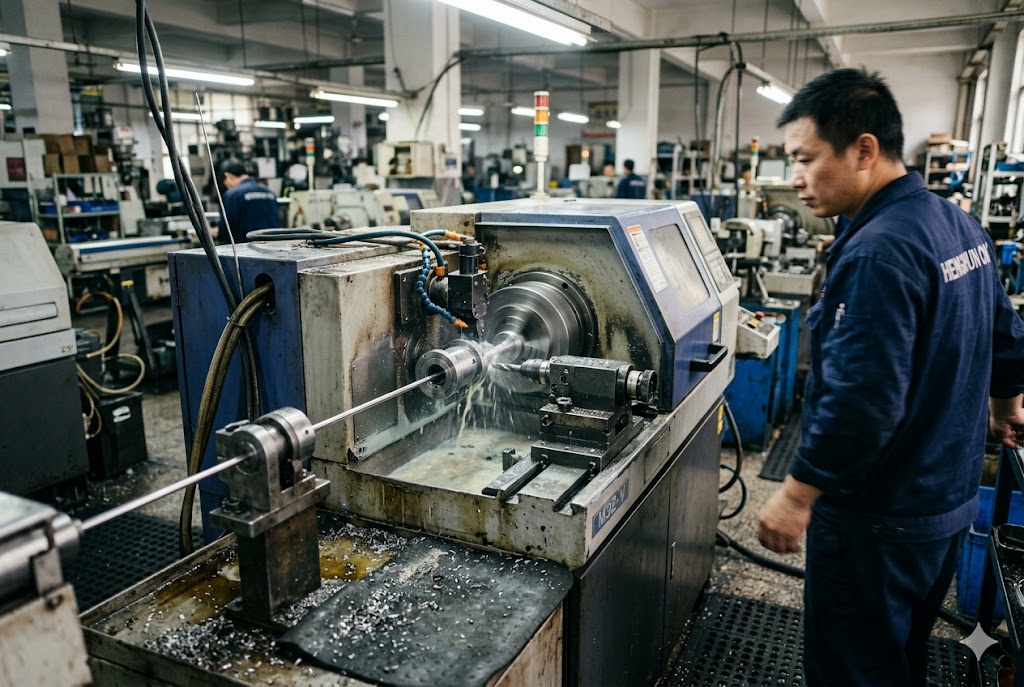
Every time our team sets up a Swiss-type lathe for a concentricity-critical job, we see the same pattern: small setup decisions made early in the run have an outsized effect on coaxiality at the end. Buyers who have dealt with eccentric parts from overseas suppliers know exactly how costly that can be — rejected shipments, line stoppages, and difficult conversations.
Concentricity on Swiss-type CNC turned parts is controlled through a combination of guide bushing condition, bar stock quality, single-setup machining, and thermal stability. When all four variables are managed correctly, Swiss-type lathes can reliably hold total runout of 0.005mm or better on diameters under 32mm in production volume.
The sections below break down each control point. If you are writing a drawing, specifying an inspection method, or qualifying a Chinese supplier for Swiss-turned parts, this is a practical reference — not a textbook summary.
What Factors in a Swiss-Type Lathe Setup Most Commonly Cause Concentricity Errors?
We see concentricity failures at every stage of a production run, and most of them trace back to the same four root causes. The machine itself is rarely the problem. Setup decisions — and the condition of consumables — are where things go wrong.
The most common causes of concentricity error in a Swiss-type lathe setup are: a worn or misadjusted guide bushing, inconsistent bar stock diameter, thermal axis shift during warm-up, and eccentric clamping caused by a worn collet. Any one of these can push runout beyond tolerance before the first part reaches the inspector.

The Guide Bushing: The First Line of Defense
The guide bushing is the mechanical core of Swiss-type turning 1. It supports the bar stock within 1–2mm of the cutting zone. This almost eliminates deflection. No other turning configuration gets the support point this close to the tool.
But the bushing only works if it is in good condition. For the guide bushing to protect concentricity, it must hold a coaxiality of 0.0002" or better. A worn bushing — even one that looks fine visually — directly corrupts part coaxiality. No amount of spindle quality fixes a bad bushing.
There are two types: fixed and rotary. Here is how they compare:
| Bushing Type | How It Works | Best For | Concentricity Limit |
|---|---|---|---|
| Fixed | Grips stationary bar as it rotates | Tight concentricity, small diameters | ±0.0001" or better |
| Rotary | Spins with the bar stock | General turning, longer bars | ±0.0005" typical |
For concentricity callouts tighter than ±0.0005", specify a fixed guide bushing 2. Rotary bushings are adequate for looser work, but they should not be used when sub-half-micron coaxiality is required.
Bar Stock Quality Is Upstream of Everything
The machine cannot fix bad bar stock. If the incoming material has runout of 0.001", the finished part will typically hold no better than ~0.0006" runout — even on a well-maintained Swiss machine with a perfect bushing.
This means raw material qualification is not optional for concentricity-critical parts. Specify h6 tolerance or better ground stock 3. Require a material certificate that includes diameter consistency data. Treat this as a prerequisite, not an upgrade.
Thermal Growth During Warm-Up
Spindle and headstock thermal growth causes slow axis shift 4 over time. On older machines, or machines without active coolant temperature control, this shift is most pronounced during the first 20–30 parts of a run. Those early parts should be treated as suspect for concentricity until thermal equilibrium is reached.
Better Swiss machines use thermally symmetric frame designs and temperature-controlled coolant to minimize this. When qualifying a supplier, ask specifically how they handle thermal warm-up for tolerance-critical runs.
Collet Wear: Overlooked in High-Volume Shops
Collet condition 5 is a frequently missed variable. A worn collet with uneven jaw contact creates eccentric clamping. In Chinese shops running high-volume Swiss parts, collet service intervals are often extended beyond what concentricity-critical work permits.
For parts with runout callouts tighter than 0.005mm, require documented collet replacement intervals in the quality plan. This is a straightforward contractual requirement, and it has a direct effect on measurement consistency across a production run.
| Variable | Effect on Concentricity | Control Method |
|---|---|---|
| Guide bushing wear | Directly corrupts coaxiality | Inspect and replace per schedule |
| Bar stock runout | Sets a floor for part runout | Specify h6 ground stock |
| Thermal growth | Causes axis shift during warm-up | Monitor first 20–30 parts |
| Collet condition | Creates eccentric clamping | Document replacement intervals |
How Do I Specify Concentricity Versus Total Runout on My Drawing, and Which Is Easier to Verify?
When drawings come to us from US buyers, we see both symbols used — sometimes interchangeably. They are not the same, and the distinction matters more when the work is going to a Chinese supplier.
On drawings for Swiss-turned parts, specify total runout or circular runout instead of the GD&T concentricity symbol. Runout is measured directly with a dial indicator against a datum diameter and is faster, more repeatable, and less prone to inter-laboratory disputes than true concentricity, which requires deriving a median axis from opposing-point midpoints.

Why the Concentricity Symbol Causes Problems
True GD&T concentricity 6 is metrologically intensive. It requires the inspector to identify the derived median axis — a line constructed from the midpoints of opposing-point pairs across the full length of a cylinder. This is not a simple dial indicator measurement. It requires a CMM and careful feature construction.
The problem is that different CMM operators can construct this axis differently if the procedure is not explicitly defined. This creates inter-laboratory variation. A part that passes inspection at your supplier's factory may fail at your incoming QC lab — not because the part changed, but because the axis was derived differently.
Runout avoids this problem. It is measured directly: fix the datum diameter in a reference frame, rotate the part, and read the total indicator movement. The result is objective and repeatable.
When to Use Each Symbol
| Callout | What It Controls | Measurement Method | Best Used When |
|---|---|---|---|
| Concentricity (GD&T) | Median axis position | CMM with axis derivation | Rarely — only when median axis position is the true functional requirement |
| Circular Runout | Variation at one cross-section | DTI against datum diameter | Controlling eccentricity at a specific feature |
| Total Runout | Variation across full surface | DTI swept along datum axis | Controlling both eccentricity and taper/form across a length |
For most Swiss-turned parts, total runout 7 is the right callout. It captures both positional eccentricity and form variation along the axis, and it is directly measurable without complex CMM feature construction.
Defining the Datum Correctly
The datum reference must be explicitly tied to a specific turned diameter. Never reference a theoretical axis on drawings going to Chinese suppliers. Suppliers using manual CMM setups will construct the datum differently if the reference feature is ambiguous.
The datum feature should be the largest, most accessible cylindrical surface that reflects the actual functional fit. If the part seats on a specific OD in the mating assembly, that OD is the correct datum for runout callouts. This is not a minor detail — an ambiguous datum is a direct path to inspection disputes on parts that are functionally eccentric but technically "passed."
What CMM or V-Block Measurement Method Should a Factory Use to Verify My Concentricity Callout?
This is one of the most practical questions we help clients resolve before production starts. The measurement method matters as much as the tolerance itself. A wrong method can make a bad part look conformant.
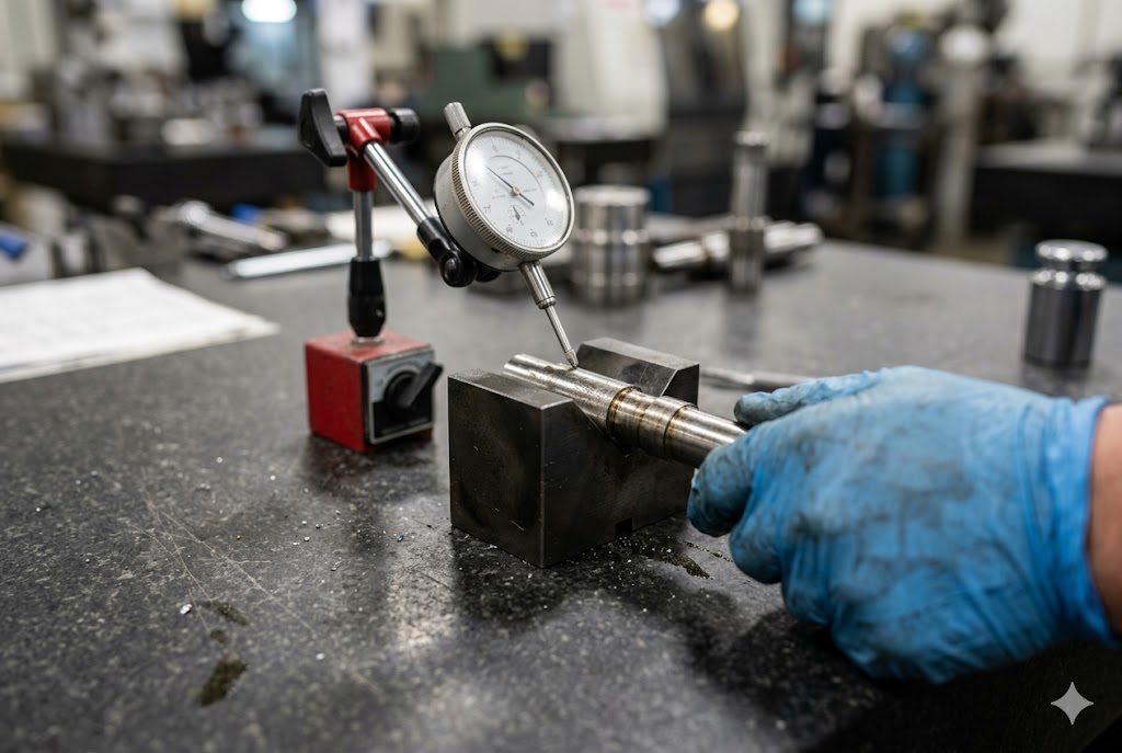
For concentricity or runout callouts tighter than 0.01mm, require CMM measurement or air-bearing spindle-based runout measurement in your inspection clause. Reject V-block and dial indicator methods as the sole verification approach, because V-block measurements conflate eccentricity with out-of-roundness and can produce misleading results on lobed datum surfaces.
The Problem With V-Block Measurement
V-block and DTI measurement is common in Chinese Swiss shops. It is fast and inexpensive. For tolerances above 0.01mm, it is adequate. Below that threshold, it introduces a systematic error that can cause genuine rejects to appear conformant.
Here is why: when you place a part in a V-block and rotate it, the V-block reads the combined effect of eccentricity and out-of-roundness. If the datum diameter is slightly lobed — a common form error in bar stock — the lobe acts as a cam and causes the part to oscillate in the V-block. The DTI reading captures this oscillation as if it were runout. A part that is truly eccentric may appear to pass if the datum lobe partially cancels the eccentricity in the V-block geometry.
This is not a measurement error a supplier will catch without the right process. It requires explicit guidance in your quality plan.
What to Require Instead
For tolerances tighter than 0.01mm, specify one of these methods:
CMM with datum simulation: The CMM 8 constructs the datum axis from the actual measured surface using a least-squares or minimum-zone algorithm. Runout of the controlled feature is then calculated relative to this constructed axis. This is objective and does not conflate form error with eccentricity.
Air-bearing spindle measurement: The part is mounted on a precision air-bearing spindle. The datum feature centers the spindle axis. The DTI reads the controlled surface as the spindle rotates. This method is the most accurate for small-diameter Swiss-turned parts and effectively isolates eccentricity from form.
Sub-Spindle Features: A Specific Risk
Multi-diameter parts with concentricity requirements across sub-spindle-completed features carry elevated risk in Chinese Swiss shops. Sub-spindle Z-axis pickup alignment is machine-dependent and is rarely verified per-part.
Contracts for these parts should require first-article CMM reports that explicitly capture runout of all sub-spindle-completed coaxial features relative to the main-spindle-defined datum. Not just overall dimensions — specifically the coaxial relationship between main-spindle and sub-spindle features.
| Measurement Method | Conflates Form + Eccentricity? | Suitable for <0.01mm? | Cost |
|---|---|---|---|
| V-block + DTI | Yes | No | Low |
| CMM datum simulation | No | Yes | Medium |
| Air-bearing spindle | No | Yes | High |
How Tight a Concentricity Tolerance Can a Swiss CNC Factory in China Reliably Hold at Volume?
This is the question buyers ask most often before placing a first order. The honest answer is: it depends on which variables are controlled, not just which machine is on the floor.
A well-equipped Chinese Swiss CNC factory with ground bar stock, maintained guide bushings, and a documented quality plan can reliably hold total runout of 0.005mm on diameters under 20mm in production volume. Tolerances tighter than 0.003mm are achievable but require engineering-level process controls and should be validated through first-article inspection before committing to volume.

What "Reliably" Means in Production Context
There is a difference between what a machine can produce on one part and what a process can produce across a full production run of 5,000 pieces. A Swiss machine can hit 0.002mm runout on a single setup with optimal conditions. Holding that across a run requires process discipline 9 that many shops do not apply by default.
The variables that degrade consistency over a run are thermal growth (early-run axis shift), collet wear (increasing clamping eccentricity as the run progresses), and guide bushing wear (gradual coaxiality loss over bar stock footage). Without monitoring and intervention points for each of these, the capability demonstrated in the first-article report will not reflect end-of-run performance.
Realistic Capability Ranges by Tolerance Level
| Runout Tolerance | Achievability at Volume | Key Requirements |
|---|---|---|
| 0.02mm | Standard — most shops | Normal bar stock, standard process |
| 0.010mm | Common with good practice | h6 bar stock, bushing inspection schedule |
| 0.005mm | Achievable with process controls | Fixed bushing, thermal warm-up protocol, CMM inspection |
| 0.003mm | Possible but requires full process engineering | Air-bearing measurement, 100% inspection, controlled environment |
| <0.002mm | Near the practical floor for production Swiss turning | Research-grade process; validate per part |
Single-Setup Machining as a Concentricity Strategy
The most reliable concentricity control strategy is to machine all coaxial diameters in a single setup without unclamping 10. When every feature shares the same spindle axis, coaxiality is guaranteed by geometry — not by fixturing repeatability. Any re-chucking, sub-spindle transfer without alignment compensation, or secondary operation re-fixturing introduces repositioning error. That repositioning error can easily exceed the concentricity budget on tighter callouts.
When reviewing a process plan from a Chinese supplier for a concentricity-critical part, ask directly: are all coaxial diameters turned in one spindle setup? If the answer involves a sub-spindle transfer, ask for the alignment compensation procedure and for first-article CMM data showing sub-spindle feature runout relative to the main-spindle datum.
What to Include in Your Quality Plan
For tolerances at or below 0.005mm, the quality plan should address:
- Bar stock specification (h6 or better, with incoming diameter consistency data)
- Guide bushing type (fixed preferred) and replacement interval
- Collet replacement interval
- Thermal warm-up protocol (minimum run time before production parts are accepted)
- Inspection method (CMM or air-bearing spindle — V-block not accepted as sole method)
- First-article CMM report covering all coaxial features, including sub-spindle-completed surfaces
- In-process frequency (minimum sampling rate per batch)
A supplier who pushes back on documenting these items is signaling that they do not have these controls in place. That is useful information before an order is placed, not after.
Conclusion
Swiss-type CNC turning is one of the most capable processes for concentricity-critical parts, but the results depend on setup discipline, material quality, and inspection rigor — not on machine brand alone. Specify total runout over concentricity, define your datum clearly, require CMM inspection for tolerances under 0.01mm, and ask for documented process controls before the first order ships.
Footnotes
1. Overview of how Swiss lathes use a guide bushing to support the workpiece and reduce deflection. ↩︎
2. Explains the differences between fixed and rotary guide bushings and when each type should be used. ↩︎
3. Covers why precision ground bar stock improves dimensional accuracy and reduces scrap in CNC machining. ↩︎
4. Details how thermal expansion during CNC machining causes axis shift and how warm-up cycles mitigate this. ↩︎
5. Technical guide on lathe collet precision ratings, runout specifications, and wear effects on CNC accuracy. ↩︎
6. Explains GD&T concentricity, why it is difficult to measure, and why it was removed from ASME Y14.5-2018. ↩︎
7. Defines total runout, how it is measured with a dial indicator, and how it differs from circular runout. ↩︎
8. Comprehensive guide to CMM inspection: how it works, probe types, and its role in GD&T verification. ↩︎
9. In-depth article on guide bushing coaxiality standards and how Swiss machining eliminates deflection errors. ↩︎
10. Explains how Swiss lathes perform multiple operations in a single setup, preserving concentricity by eliminating repositioning error. ↩︎



