 Skip to main content Skip to footer
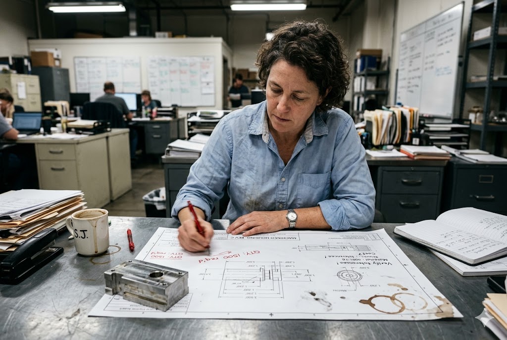
We see this problem on nearly every new project: a drawing arrives with a note that says "parts shall be clean and free of contamination." That sounds reasonable. But when a shipment fails incoming inspection and the supplier insists the parts look clean to them, that vague note gives you nothing to stand on.
To specify cleanliness requirements for machined parts, you must separately address particulate contamination and chemical film residue, reference a recognized standard such as ISO 16232 or VDA 19.1 for particles, define a gravimetric or dyne-based acceptance limit, and embed these requirements in both your drawing and purchase order.
This article breaks down each element — what to write, where to write it, and how to make it enforceable with Chinese suppliers.
What Cleaning Process Removes EDM Dielectric Fluid from Precision Machined Surfaces?
Wire EDM leaves a thin layer of dielectric fluid 1 on every cut surface. Most buyers assume a standard wash cycle takes care of it. In our experience running pre-shipment inspections at Chinese shops, that assumption gets buyers into trouble more often than they expect.
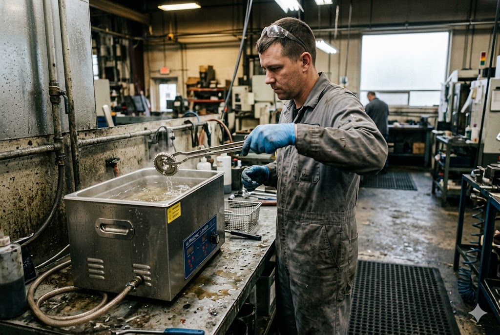
Removing EDM dielectric fluid from precision machined surfaces requires an ultrasonic cleaning cycle in an appropriate solvent or aqueous alkaline bath, followed by a clean-water rinse and forced-air or oven drying. A simple dip-and-drain wash is not sufficient for blind features, slots, or fine surface textures.
Why Dielectric Fluid Is Harder to Remove Than It Looks
EDM dielectric fluid — typically deionized water or hydrocarbon-based oil — penetrates micro-crevices created during the spark erosion process. The EDM recast layer is porous at the microscopic level. Standard spray washing does not reach these areas. Residual fluid left in place will:
- Attract particulate contamination during transit
- Interfere with adhesion in downstream coating or bonding processes
- Cause corrosion on ferrous materials within weeks of delivery
Recommended Cleaning Process Steps
The cleaning process for EDM parts should follow a defined sequence. Skipping any stage is a common shortcut taken by smaller Chinese shops under time pressure.
| Stage | Method | Purpose |
|---|---|---|
| Pre-rinse | Pressurized spray, ambient temperature | Remove loose chips and bulk fluid |
| Ultrasonic wash 2 | Aqueous alkaline or solvent bath, 40–60°C, 10–20 min | Penetrate micro-pores and recast layer |
| Rinse 1 | Clean deionized or RO water | Remove chemical residue from wash bath |
| Rinse 2 | Fresh DI water, overflow rinse | Final ionic contamination reduction |
| Drying | Forced hot air or oven, ≥60°C | Prevent flash corrosion and recontamination |
What the Supplier Must Document
Requiring the supplier to submit their cleaning process parameters as part of First Article Inspection (FAI) 3 documentation is not optional — it is the only way to verify they are running the correct process. At a minimum, request:
- Cleaning fluid chemistry (product name, concentration, pH)
- Bath temperature and cycle duration
- Agitation method (ultrasonic frequency, spray pressure)
- Rinse water quality (conductivity or resistivity target)
- Drying method and temperature
Without this disclosure, the supplier can change their process between FAI and production runs. You have no traceability. Requiring these parameters also forces them to formalize a process they may currently run informally, which alone improves consistency.
Verification After Cleaning
Verification of EDM dielectric removal can be done non-destructively using dyne pen testing. Apply a dyne solution at 36–38 dynes/cm to a representative surface area. If the fluid beads up rather than spreading, residual contamination is present. This test takes under a minute and can be performed during pre-shipment inspection without specialized lab equipment.
How Do I Define an Acceptable Cleanliness Standard for Wire EDM Parts in My QC Plan?
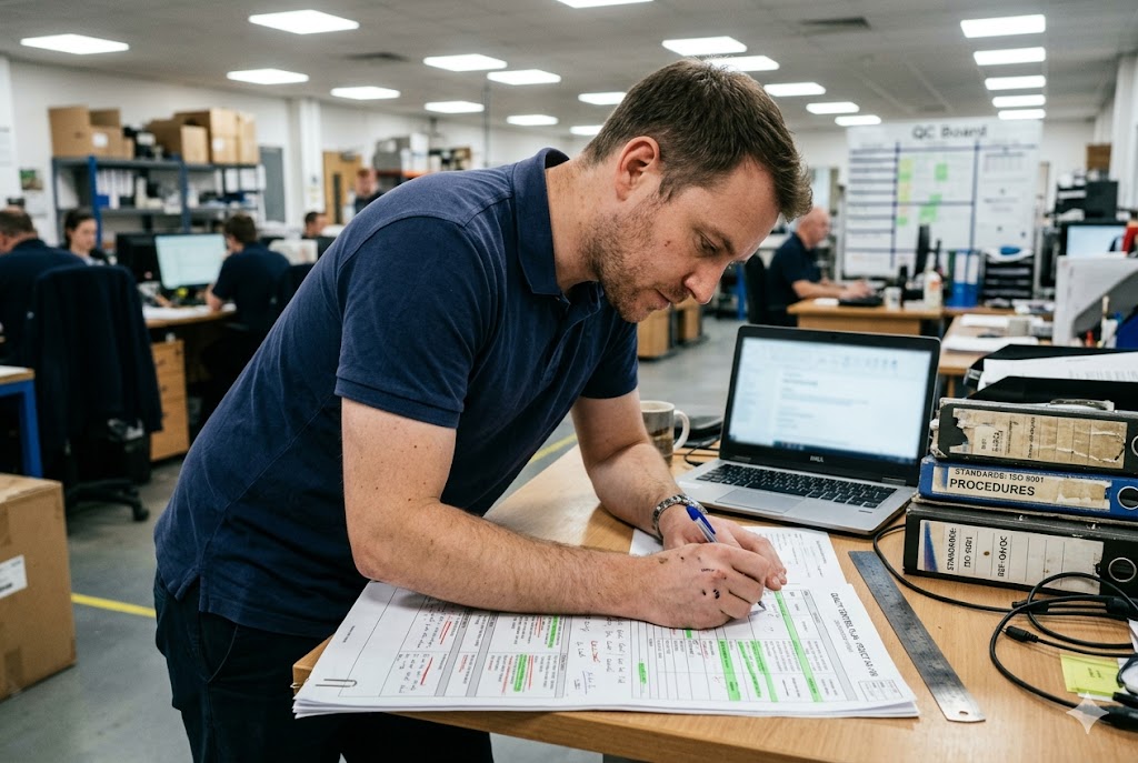
Our engineers have found that buyers typically write cleanliness requirements in one of two ways: a vague drawing note, or no note at all. Neither holds up when a dispute occurs. Writing a defensible cleanliness standard requires understanding two separate contamination classes and picking the right test method for each.
An acceptable cleanliness standard for wire EDM parts in a QC plan must separately specify a particle size and mass limit per ISO 16232 or VDA 19.1, a nonvolatile residue limit in mg/m² per a gravimetric extraction method, and a minimum surface energy threshold tested per ASTM D2578 or equivalent.
Particulate Contamination: ISO 16232 and VDA 19.1
ISO 16232 4 and VDA 19.1 5 are the two recognized international frameworks for component cleanliness measurement. Both were developed in the automotive sector but are now adopted in hydraulics, medical devices, and precision engineering. They define:
- How to extract particles from a component surface (spray, ultrasound, rinsing, or agitation)
- The extraction fluid to use
- How to filter and measure particles on a membrane
- How to express the result (particle size distribution, count, or mass)
When writing your QC plan, reference the standard by number and specify the extraction method. A note that simply says "clean per ISO 16232" is incomplete. You must define the extraction procedure, because the same part can yield different particle counts depending on how aggressively it is extracted.
| Parameter | What to Specify | Example Value |
|---|---|---|
| Standard reference | ISO 16232 or VDA 19.1 | ISO 16232:2018 |
| Extraction method | Spray / ultrasonic / rinsing | Ultrasonic, 5 min |
| Maximum particle size | Largest permissible single particle | 200 µm |
| Maximum particle count | Per size class | ≤50 particles >100 µm |
| Maximum gravimetric residue | Total mass on filter membrane | ≤1.0 mg per part |
Nonvolatile Residue: Setting a Film Cleanliness Limit
Particulate standards do not cover chemical film contamination. For cutting fluid, emulsion, rust inhibitor, and dielectric fluid residue, you need a separate acceptance limit expressed as nonvolatile residue (NVR).
IEST-STD-CC1246 6 is the aerospace-originated standard for NVR specification. It expresses contamination limits in mg per 0.1 m² of surface area. For industrial machined parts where aerospace cleanliness levels are not required, adapt this structure: specify a maximum NVR value in mg/m² determined by gravimetric measurement after solvent extraction.
A practical starting point for precision machined parts used in hydraulic or pneumatic assemblies is ≤50 mg/m² NVR. For optical, medical, or electronic applications, that limit will be tighter.
Surface Energy as a Proxy Test
Dyne testing is a fast, low-cost proxy for film contamination. ASTM D2578 7 defines the test method. The principle: a clean metal surface has high surface energy and wets readily. Residual oil or chemical film reduces surface energy and causes fluid to bead.
Specify a minimum surface energy threshold of ≥36 dynes/cm for general machined parts. For parts requiring downstream adhesive bonding, coating, or anodizing, raise this to ≥42 dynes/cm. Include this requirement in your drawing note and your incoming inspection criteria.
Tying the Limit to a Functional Rationale
Set your particle size limit based on the smallest critical clearance the part will see in service — typically the minimum orifice, bearing clearance, or valve seat gap. A particle larger than that clearance can cause a functional failure. Documenting this rationale in your design record also makes the specification defensible in a supplier dispute.
Should Residual Fluid and Contamination Be Checked During Pre-Shipment Inspection?
When we conduct pre-shipment inspections at Chinese factories on behalf of US clients, cleanliness is one of the most commonly skipped checkpoints. Dimensional checks and visual appearance get attention. Surface contamination does not — unless it is written into the inspection criteria before the inspector walks in the door.
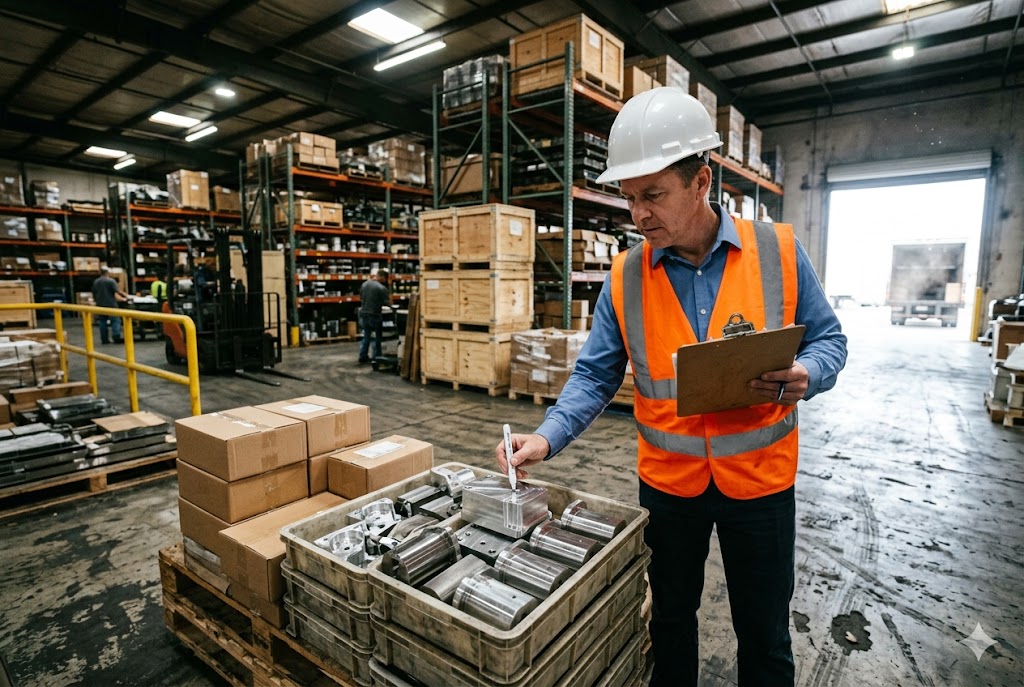
Yes, residual fluid and contamination must be included in pre-shipment inspection criteria. Dimensional conformance does not confirm cleanliness. Without a defined sampling plan and specific test methods written into the inspection scope, the PSI inspector will default to visual assessment, which is insufficient.
What a Cleanliness PSI Checkpoint Looks Like
A cleanliness check during PSI does not require a full laboratory. Practical methods available on the factory floor include:
| Test Method | What It Detects | Equipment Required | Time per Sample |
|---|---|---|---|
| Dyne pen test | Chemical film (residual oil/fluid) | Dyne solution set, ≤$50 | 1–2 minutes |
| White glove wipe | Particulate contamination (loose) | Clean white cloth | 1 minute |
| UV light inspection | Certain fluorescent fluids and oils | UV lamp | 2 minutes |
| Gravimetric NVR | Film contamination by mass | Solvent, balance (lab-grade) | 30–60 minutes |
For most PSI scenarios, dyne pen testing and white glove wipe checks are practical and fast. Gravimetric NVR requires lab conditions and is more appropriate for first article inspection than shipping lot verification.
Defining the Sampling Plan
Do not rely on 100% inspection for cleanliness. It is impractical for bulk hardware. Instead, reference a statistical sampling plan such as AQL 1.0 per ANSI/ASQ Z1.4 8 for attribute inspection. This defines how many parts to inspect from a given lot size and what the accept/reject threshold is.
Write the sampling plan into the purchase order and the quality plan. If any sampled unit fails the cleanliness check, require a full-lot resubmission — not just re-cleaning of the failed sample. Allowing re-cleaning of individual samples without lot resubmission is the most common evasion tactic we see in production environments.
Linking PSI Sign-Off to Payment
Structure payment milestones so that PSI sign-off, including cleanliness verification, is a release condition for the final payment tranche. When the supplier knows that the final 30% payment is held until the inspector confirms cleanliness, they have a direct financial incentive to comply. This is more effective than any drawing note alone.
The Two-Point Inspection Principle
Specify cleanliness requirements at two distinct points: the as-machined baseline (before cleaning) and the clean-at-ship condition (after final cleaning, before packaging). Requiring documentation of both conditions prevents the supplier from simply re-washing a failing part and resubmitting it. The as-machined baseline also gives you data on whether the machining process itself is generating excessive contamination.
What Packaging Method Prevents Re-Contamination of Cleaned Wire EDM Parts During Transit?
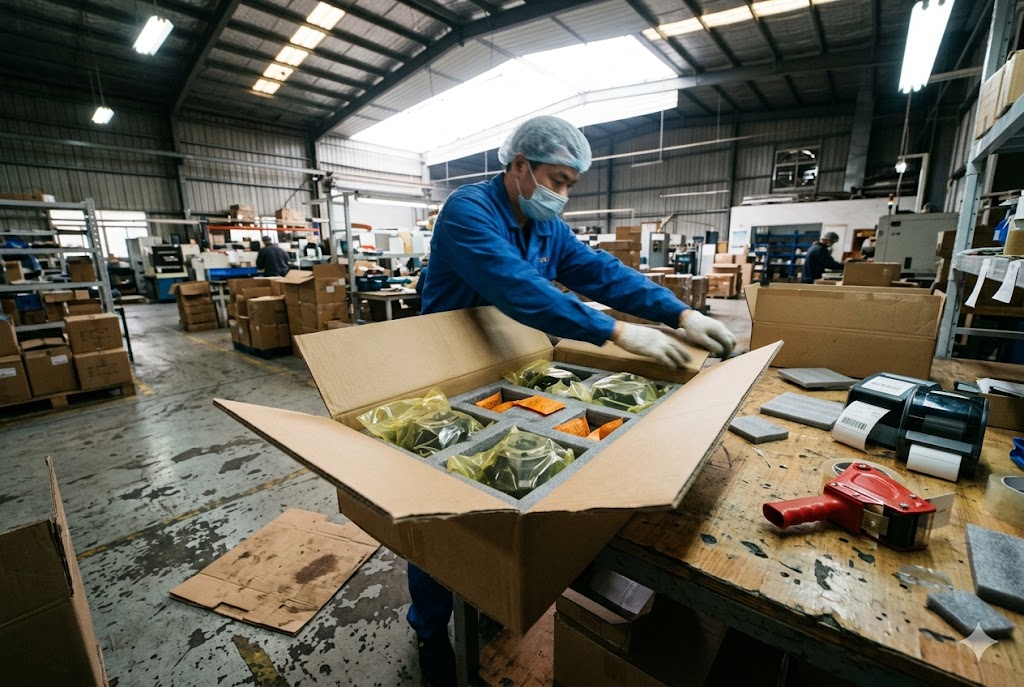
Getting a part clean is half the job. Keeping it clean through transit, customs handling, and final delivery is the other half — and it is the half that most specifications ignore entirely. Our team has received shipments that passed PSI cleanliness checks but arrived at the customer's dock visibly contaminated because the packaging failed.
To prevent re-contamination of cleaned wire EDM parts during transit, each part must be individually sealed in a VCI (vapor corrosion inhibitor) poly bag immediately after final cleaning, placed in a rigid or semi-rigid container with desiccant, and sealed before leaving the clean area. Packaging must be treated as a continuation of the cleanliness requirement, not a logistics afterthought.
Why Standard Poly Bags Are Not Enough
Standard polyethylene bags offer physical separation but provide no chemical protection. Ferrous and non-ferrous machined parts are vulnerable to:
- Moisture-driven oxidation and flash corrosion (especially during ocean freight through humidity-variable environments)
- Particulate ingress through unsealed bag openings
- Cross-contamination from adjacent parts or packaging materials that off-gas
VCI bags 9 release a vapor-phase corrosion inhibitor that forms a monomolecular protective layer on the metal surface. This does not add contamination — VCI chemistry is compatible with most downstream processes including painting, plating, and assembly. Specify VCI bags rated for the specific metal type (ferrous vs. non-ferrous VCI chemistry differs).
Packaging Specification Table
| Packaging Element | Requirement | Notes |
|---|---|---|
| Primary bag | VCI poly bag, heat-sealed | Sized to minimize air volume inside bag |
| Secondary container | Rigid carton or foam-lined case | Prevents physical contact between parts |
| Desiccant | Silica gel or molecular sieve, quantity per MIL-D-3464 10 or equivalent | Replace for every shipment, do not reuse |
| Seal timing | Bag sealed within 30 minutes of final cleaning | Prevents recontamination during handling |
| Label | Part number, lot number, clean-at-ship date | Enables traceability |
Specifying Packaging in the Purchase Order
Draw note language alone does not govern packaging. Packaging requirements must appear in the purchase order as a delivery condition. State:
- Bag type and material specification
- Seal method (heat seal, not twist-and-tie)
- Desiccant type and quantity
- Maximum time between cleaning completion and sealing
- Any labeling requirements for traceability
Inspection of Packaging at PSI
During pre-shipment inspection, verify packaging integrity before signing off. Check that:
- Bags are heat-sealed, not folded or taped
- Desiccant is present and not saturated (color indicator desiccant is preferable)
- No visible particulate inside the sealed bag
- Parts are not in contact with each other inside the container
A packaging failure at PSI is a hold condition, the same as a dimensional or cleanliness failure. Treat it that way in your quality plan.
Conclusion
Cleanliness is an engineering requirement, not a housekeeping instruction. Write it with specific standards, defined test methods, and enforceable acceptance limits — then extend those requirements to inspection, packaging, and payment terms.
Footnotes
1. Overview of wire EDM process, dielectric fluid function, and recast layer formation. ↩︎
2. Explains ultrasonic cleaning cavitation process for removing contaminants from machined parts. ↩︎
3. Guide to AS9102 First Article Inspection Reports and required documentation forms. ↩︎
4. Official ISO 16232:2018 standard page for road vehicle component cleanliness requirements. ↩︎
5. Overview comparing VDA 19.1 and ISO 16232 cleanliness verification standards. ↩︎
6. Explains IEST-STD-CC1246 cleanliness levels, including particulate and NVR contamination limits. ↩︎
7. Details ASTM D2578 dyne testing methodology for evaluating metal surface cleanliness. ↩︎
8. ASQ overview of ANSI/ASQ Z1.4 sampling plans for attribute inspection. ↩︎
9. Explains how VCI bags protect metal parts from corrosion during shipping. ↩︎
10. MIL-D-3464E specification details for activated bagged desiccants used in packaging. ↩︎



